
Page 456 - Design of Reinforced Masonry Structures
P. 456
7.18 CHAPTER SEVEN
TABLE 7.1 In-plane Deflections of Walls due to Shear as a
Percentage of Total Deflection
Aspect ratio, h/d Cantilever wall Fixed-ended wall
0.25 92.3 98.0
0.50 75.0 92.0
0.75 57.1 84.2
1.00 42.9 75.0
1.50 25.0 57.1
2.00 15.8 42.9
2.50 10.7 32.4
3.00 7.7 25.0
3.50 5.8 19.7
4.00 4.5 15.8
5.00 2.9 10.7
6.00 2.0 7.7
8.00 1.2 4.5
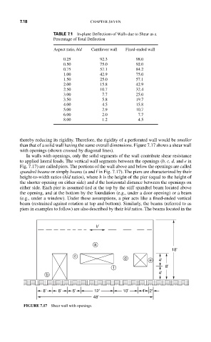
thereby reducing its rigidity. Therefore, the rigidity of a perforated wall would be smaller
than that of a solid wall having the same overall dimensions. Figure 7.17 shows a shear wall
with openings (shown crossed by diagonal lines).
In walls with openings, only the solid segments of the wall contribute shear resistance
to applied lateral loads. The vertical wall segments between the openings (b, c, d, and e in
Fig. 7.17) are called piers. The portions of the wall above and below the openings are called
spandrel beams or simply beams (a and f in Fig. 7.17). The piers are characterized by their
height-to-width ratios (h/d ratios), where h is the height of the pier (equal to the height of
the shorter opening on either side) and d the horizontal distance between the openings on
either side. Each pier is assumed tied at the top by the stiff spandrel beam located above
the opening, and at the bottom by the foundation (e.g., under a door opening) or a beam
(e.g., under a window). Under these assumptions, a pier acts like a fixed-ended vertical
beam (restrained against rotation at top and bottom). Similarly, the beams (referred to as
piers in examples to follow) are also described by their h/d ratios. The beams located in the
V
a 18'
c
d
e 4'
f 8'
b 4'
8' 8' 6' 12' 10' 4' 2'
48'
FIGURE 7.17 Shear wall with openings.