
Page 461 - Design of Reinforced Masonry Structures
P. 461
SHEAR WALLS 7.23
y
k 1
k 2
P
k 3
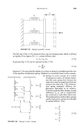
FIGURE 7.19 “Springs in parallel” concept.
The left side of Eq. (7.32) represents force per unit displacement, which is defined
as rigidity. If we express P/y = k = system stiffness, then
k = k + k + k (7.33)
1
3
2
In general, Eq. (7.33) can be expressed as Eq. (7.34):
n
k = ∑ k (7.34)
i
i=1
Equation (7.34) states that the rigidity of a system of springs in parallel equals the sum
of the rigidities of individual springs. Method A is essentially based on this concept.
(b) Springs in series concept: In a system
of springs in a series, all springs experi-
ence the same spring force because the
same force must be transferred from one
k 1
y 1 = P spring to the other (Fig. 7.20). However,
k 1
k 1 each spring undergoes different dis-
placement depending on its stiffness.
k 2 y 1
Consider again that three springs, having
stiffnesses, k , k , and k , respectively,
3
1
2
k 3 P are connected to each other end-to-end.
k 2 y 2 =
can be expressed as spring force divided
y 1 + y 2 k 2 The displacements of these three springs
by spring stiffness. Thus,
P
y = P
y 1 + y 2 + y 3 k 3 y =
k 3 1
k
1
y = P (7.35)
2
k 2
P y = P
3
FIGURE 7.20 “Springs in series” concept. k 3