Page 457 - Design of Reinforced Masonry Structures
P. 457
SHEAR WALLS                       7.19

         upper portion of a cantilevered shear wall (above the openings and extending to the top, a
         in Fig. 7.17) should be assumed fixed at the bottom and free to rotate at the top. However,
         a beam located between the openings and the floor below should be treated as fixed at both
         the top and bottom.
           In calculating the relative rigidity of a shear wall, it is necessary to calculate the relative
         rigidity of the entire wall as well as that of its piers and beams. It is generally assumed that
         cantilevered conditions exist for walls in one- or two-story buildings taken in their entirety;
         piers and beams within the walls can be considered as cantilevered or fixed. For example, a
         shear wall in a single-story building taken as a whole would be considered as cantilevered,
         but piers within the wall may be considered as fixed at both top and bottom.
           When lateral forces are transferred from a rigid diaphragm to shear walls with differ-
         ent rigidities, the shear walls share the lateral load in proportion to their rigidities. This is
         an important design principle: the wall with greater rigidity would attract larger share of
         the lateral load. Because the walls sharing lateral load from a diaphragm, in all likelihood,
         would be of the same thickness and masonry compressive strength, it is only necessary to
         determine the relative rigidity of a shear wall for design purposes.
           When determining the relative rigidity of a perforated shear wall, the quantity of interest
         is its deflection; the rigidity of the wall is then determined as the reciprocal of its deflec-
         tion. Whereas the deflection of a solid wall can be determined directly from Eqs. (7.7) or
         (7.13) (as applicable), determination of the deflection of a perforated wall is a bit tricky.
         The calculations get more involved as the number of openings increases; particularly when
         the heights of openings are different, or the openings are located at different elevations
         within the wall.
           In a shear wall building, analysis for a shear wall with openings typically involves two
         important steps: (a) determination of shear from the diaphragm to the wall, and (b) distri-
         bution of the wall shear to its piers. In a masonry/concrete shear wall building with rigid
         diaphragms, the total diaphragm shear V is distributed to various shear walls in proportion
         to their relative rigidities. The shear in any individual pier of a wall is then determined by
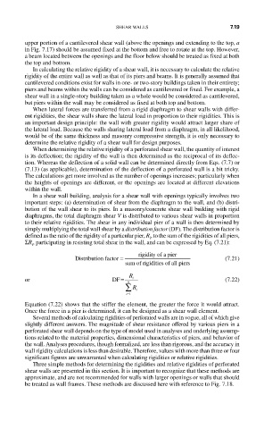
         simply multiplying the total wall shear by a distribution factor (DF). The distribution factor is
         defined as the ratio of the rigidity of a particular pier, R , to the sum of the rigidities of all piers,
                                              i
         ΣR , participating in resisting total shear in the wall, and can be expressed by Eq. (7.21):
           i
                        Distribution factor =  rigidity of a pier      (7.21)
                                       sum of rigidities of all piers
                                           f
         or                        DF =  n R i                       (7.22)
                                       ∑ R i
                                       − i 1
         Equation (7.22) shows that the stiffer the element, the greater the force it would attract.

         Once the force in a pier is determined, it can be designed as a shear wall element.
           Several methods of calculating rigidities of perforated walls are in vogue, all of which give
         slightly different answers. The magnitude of shear resistance offered by various piers in a
         perforated shear wall depends on the type of model used in analyses and underlying assump-
         tions related to the material properties, dimensional characteristics of piers, and behavior of
         the wall. Analyses procedures, though formalized, are less than rigorous, and the accuracy in
         wall rigidity calculations is less than desirable. Therefore, values with more than three or four
         significant figures are unwarranted when calculating rigidities or relative rigidities.
           Three simple methods for determining the rigidities and relative rigidities of perforated
         shear walls are presented in this section. It is important to recognize that these methods are
         approximate, and are not recommended for walls with larger openings or walls that should
         be treated as wall frames. These methods are discussed here with reference to Fig. 7.18.

