
Page 462 - Design of Reinforced Masonry Structures
P. 462
7.24 CHAPTER SEVEN
If the total displacement of the spring system is y, then y equals the sum of three
quantities given by Eq. (7.36):
y = y + y + y = P + P + P = P ⎛ 1 + 1 + 1 ⎞ ⎟ (7.36)
⎜
1 2 3 ⎝ k ⎠
k 1 k 2 k 3 k 1 k 2 3
If we define P/y = k = system stiffness, then Eq. (7.36) can be expressed as
1 1 1 1
= + + (7.37)
k k 1 k 2 k 3
In general, Eq. (7.37) can be expressed as Eq. (7.38):
n
1 = ∑ 1 (7.38)
k i= 1 k i
Equation (7.38) states that the reciprocal of the system stiffness equals the sum of
the reciprocals of stiffnesses of individual springs.
Application of the three above described methods is illustrated by Examples 7.4 through
7.8. In a masonry-building project where several perforated walls are encountered, calcu-
lation of rigidities of various piers becomes a time-consuming task. For computational
efficiency, design aids (Tables A.26 and A.27) can be used.
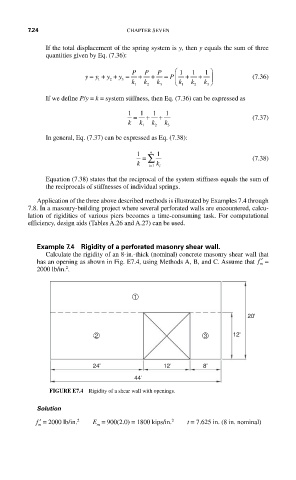
Example 7.4 Rigidity of a perforated masonry shear wall.
Calculate the rigidity of an 8-in.-thick (nominal) concrete masonry shear wall that
has an opening as shown in Fig. E7.4, using Methods A, B, and C. Assume that ′ f =
m
2
2000 lb/in. .
1
20'
2 3 12'
24' 12' 8'
44'
FIGURE E7.4 Rigidity of a shear wall with openings.
Solution
2
2
′ f = 2000 lb/in. E = 900(2.0) = 1800 kips/in. t = 7.625 in. (8 in. nominal)
m m