Page 466 - Design of Reinforced Masonry Structures
P. 466
7.28                      CHAPTER SEVEN

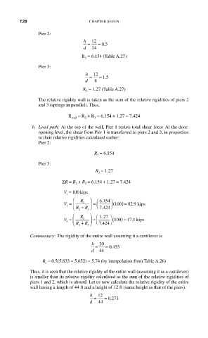
                Pier 2:
                                 h  12
                                         .
                                   =  = 05
                                 d  24
                                R  = 6.154 (Table A.27)
                                 2
                Pier 3:
                                  h  12
                                    =  = 15
                                         .
                                  d  8
                                 R  = 1.27 (Table A.27)
                                  3
                The relative rigidity wall is taken as the sum of the relative rigidities of piers 2
                and 3 (springs in parallel). Thus,

                           R wall  = R  + R  = 6.154 + 1.27 = 7.424
                                     3
                                 2
             b.  Load path: At the top of the wall, Pier 1 resists total shear force  At the door-
                                                               .
                opening level, the shear from Pier 1 is transferred to piers 2 and 3, in proportion
                to their relative rigidities calculated earlier:
                Pier 2:
                                     R  = 6.154
                                      2
                Pier 3:
                                      R = 1.27
                                       3
                         ΣR = R  + R  = 6.154 + 1.27 = 7.424
                              2
                                  3
                         V = 100kips
                          1
                             ⎛  R  ⎞   6 154 ⎞
                           V =  ⎜ ⎝  R + 2 R ⎠ ⎟  =  ⎛ .  ( 100) =  82 9 . kips
                                               0
                                       7 424 ⎠
                          2
                                      ⎝ .
                             ⎛  2 R  3 ⎞  ⎛ .
                                       127 ⎞
                         V 3  =  ⎜  3  ⎟  =  ( 1 100) = 17 1 .kips
                                       7 424 ⎠
                             ⎝ R 2  + R 3 ⎠  ⎝ .
             Commentary: The rigidity of the entire wall assuming it a cantilever is
                                     h =  20  = 0 455.
                                    d  44
                 R  = 0.5(5.833 + 5.652) = 5.74 (by interpolation from Table A.26)
                  c
             Thus, it is seen that the relative rigidity of the entire wall (assuming it as a cantilever)
             is smaller than its relative rigidity calculated as the sum of the relative rigidities of
             piers 1 and 2, which is absurd. Let us now calculate the relative rigidity of the entire
             wall having a length of 44 ft and a height of 12 ft (same height as that of the piers).
                                   h  12
                                     =   = 0 273
                                           .
                                   d   44

