
Page 468 - Design of Reinforced Masonry Structures
P. 468
7.30 CHAPTER SEVEN
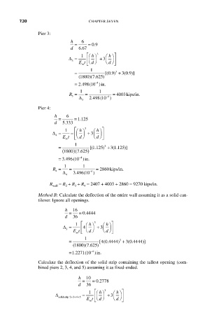
Pier 3:
h 6
= = 09 .
.
d 667
⎛ ⎡
h ⎞
1
∆ 3 = Et ⎝ ⎠ 3 3 ⎛ ⎝ h ⎞ ⎤ ⎥ ⎦
⎜ ⎟ + ⎜ ⎟ ⎥
⎢
d ⎠
d
m ⎣
= 1 [( 09 . ) 3 + 3 09 . )]
(
( 1800 7 625)
)( .
−4
(
.
= 2 498 10 )in.
)
R = 1 = 1 = 4003 kips/in .
∆ 3 . 2 498 (10 )
3 4 −
Pier 4:
h 6
= = 1 125
.
d 5 333
.
⎛ ⎡
h ⎞ ⎤
3
⎛
h ⎞
∆ = 1 = ⎜ ⎟ + ⎜ ⎟ ⎥
⎢
3
4
Et ⎣ ⎣ ⎝ d ⎠ ⎝ d ⎠ ⎦
m
= 1 [( . 3 +3 1 125)]
( .
1 125)
(1800 )(7 625 )
.
4 −
= 3.4496 10( )in.
R = 1 = 1 = 2860 kips/inn.
∆ 3 496 10 )
4 4 −
(
.
4
R wall = R + R + R = 2407 + 4003 + 2860 = 9270 kips/in.
3
2
4
Method B: Calculate the deflection of the entire wall assuming it as a solid can-
tilever. Ignore all openings.
h 16
= = 0 4444
.
d 36
1 ⎡ ⎛ h ⎞ 3 ⎛ h ⎞ ⎤
∆ = ⎢ ⎢ 4 ⎜ ⎟ + ⎜ ⎟ ⎥
3
3
Et ⎝ d ⎠ ⎝ d ⎠ ⎦
m ⎣
( 1800 7 625)
= 1 [( . 3 + 3 0 4444)]
4 0 4444)
( .
)( .
4 −
(
=1 2271 10 )in.
1.
Calculate the deflection of the solid strip containing the tallest opening (com-
bined piers 2, 3, 4, and 5) assuming it as fixed-ended.
h 10
= = 0 2778
.
d 36
3
⎛ ⎞ ⎤
h ⎞
h
∆ = 1 ⎢ ⎛ ⎡ ⎜ ⎟ + ⎜ ⎟ ⎥
3
solidstrip 234 Et ⎝ ⎠ ⎠ ⎝ ⎠ ⎦
++ +5
m ⎣
d
d