Page 472 - Design of Reinforced Masonry Structures
P. 472
7.34                      CHAPTER SEVEN

           Summary:
                Method A: R = 9270 kips/in.
                Method B: R = 5444 kips/in.
                Method C: R = 5944 kips/in.
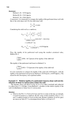
             Commentary: It is instructive to compare the rigidity of the perforated shear wall with
             that of the solid shear wall. For the solid shear wall,

                                    h  16
                                           .
                                      =  = 0 444
                                    d  36
             Considering the solid wall as a cantilever,
                                   ⎡
                                             h
                                      h
                         ∆   =  1  = 4  ⎛ ⎞  3  3 ⎛ ⎞ ⎤
                                   ⎢
                                     ⎜ ⎟ + ⎜ ⎟ ⎥
                          solid      ⎝ ⎠    ⎝ ⎠
                               Et  ⎣  d      d  ⎦
                                m
                                          4 0 444 +
                             =     1     [( .  ) 3  3 0 444)]
                                                   (
                                                     .
                               ( 1800 7 625)
                                  0)( .
                             = 1 2256 10 ))in.
                                      4 −
                               .
                                   (
                         R   =  1  =    1     = 8159 kips/in
                          solid  ∆  1 2256 10 )
                                           −4
                                     .
                                         (
                                solid
             Thus, the rigidity of the perforated wall (using the smallest calculated value,
             Method B) is
                    ⎛  5444 ⎞
                     ⎜   ⎟ ( 100 =)  66 7 . percent of the rigiddity of the solid wall
                    ⎝ 8159 ⎠
             The rigidity of the perforated wall based on Method C is
                    ⎛ 5944 ⎞
                     ⎜   ⎟ ( 100 =  72 8 percent of the rigiddity of the solid wall
                                 .
                             )
                    ⎝ 8159 ⎠
             It is also instructive to compare the rigidity of the solid wall, 8159 kips/in., with the
             rigidity of the perforated wall given by Method A, 9270 kips/in. (>8159 kips/in.). The
             reason for this discrepancy was explained earlier.
           Example 7.7  Relative rigidity of a perforated masonry shear wall and dis-

           tribution of shear to various piers within the wall.
             The masonry shear wall shown in Fig. E7.6 is 8 in. thick (nominal) and subjected
           to a shear force V = 100 kips. Using Method C, calculate (a) the relative rigidity of the
           wall, (b) distribution of shear force in various piers.
           Solution
             a.  Observe that Pier 1 is fixed at the base and free to rotate at the top; accordingly,
                it would be treated as a cantilever. By the virtue of their positions, Piers 2, 3, 4,
                and 5 would be treated as fixed at both ends. Relative rigidities of all five piers
                are shown in Table E7.7 as determined from Tables A.26 and A.27.

