
Page 474 - Design of Reinforced Masonry Structures
P. 474
7.36 CHAPTER SEVEN
b. Distribution of shear in piers:
V = 100 kips
1
⎛ 1 753 ⎞
.
)
V = ⎜ ⎟ ( 100 = 31..39 kips
1 753 3 831 ⎠
2
⎝ . + .
⎛ . 3 831 ⎞
)
V = ⎜ ⎟ (100 = 668 61. kips
++
+
34 5 ⎝ . 1 753 3 .831 ⎠
⎛ 2 916 ⎞
.
68 61 =
V = ⎜ ⎟ ( . ) 40 01 kips
.
3 2 916 2 084 ⎠
⎝ . + .
⎛ 2 084 ⎞
.
68 61 =
V = ⎜ ⎟ ( . ) 28 60 kips
.
4 4 2 916 2 084 ⎠
⎝ . + .
=
+
.
.
.
V = V 3 + V 4 = 40 01 28 60 68 61 kips
5 5
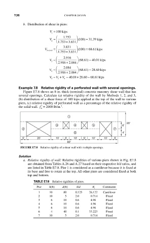
Example 7.8 Relative rigidity of a perforated wall with several openings.
Figure E7.8 shows an 8-in.-thick (nominal) concrete masonry shear wall that has
several openings. Calculate (a) relative rigidity of the wall by Methods 1, 2, and 3,
(b) distribution of a shear force of 100 kips applied at the top of the wall to various
piers, (c) relative rigidity of perforated wall as a percentage of the relative rigidity of
2
the solid wall. ′ f = 2000 lb/in. .
m
1
20'
3 4 5 6'
2 7
6 4'
5' 20' 10' 5' 10' 5' 10' 10' 5'
80'
FIGURE E7.8 Relative rigidity of a shear wall with multiple openings.
Solution
a. Relative rigidity of wall: Relative rigidities of various piers shown in Fig. E7.8
are obtained from Tables A.26 and A.27 based on their respective h/d ratios, and
are listed in Table E7.8. Pier 1 is considered as a cantilever because it is fixed at
its base and free to rotate at the top. All other piers are considered fixed at both
top and bottom.
TABLE E7.8 Relative rigidities of piers.
Pier h(ft) d(ft) h/d R r Comments
1 10 80 0.125 26.122 Cantilever
2 10 5 2.0 0.714 Fixed
3 6 10 0.6 4.96 Fixed
4 6 10 0.6 4.96 Fixed
5 6 10 0.6 4.96 Fixed
6 4 40 0.1 33.223 Fixed
7 10 5 2.0 0.714 Fixed