
Page 465 - Design of Reinforced Masonry Structures
P. 465
SHEAR WALLS 7.27
1 1 1 1 1 −
1 3968)(110 )
= + = + = (. 5
.
,
R ++ R R + 24 074 10 189
12 3 1 2 3
R = 7159 kips/in.
1+2+3
The rigidity of the wall is 7159 kips/in.
Summary:
Method A: R = 10,189 kips/in.
Method B: R = 6109 kips/in.
Method C: R = 7159 kips/in.
Commentary: It is instructive to compare the rigidity of the perforated wall with that of
the solid wall. The gross deflection of the solid wall was calculated for Method B:
-5
∆ gross = (12.6706)(10 ) in.
R = 1 = 1 = 7892 kips/in..
∆ (. )(
solid −5
12 6706 10 )
gross
The rigidity of the whole wall, 7892 kips/in., is smaller than the sum of the rigidities
of the three component piers calculated by Method 1 (10,189 kips/in.), which obvi-
ously is absurd, and points out the approximation inherent in Method 1.
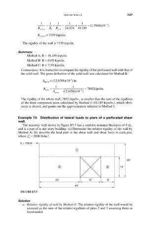
Example 7.5 Distribution of lateral loads to piers of a perforated shear
wall.
The masonry wall shown in Figure E7.5 has a uniform nominal thickness of 8 in.,
and is a part of a one-story building. (a) Determine the relative rigidity of the wall by
Method A; (b) describe the load path in the shear wall and shear force in each pier,
2
where ′ f = 2000 lb/in. .
m
V = 100 K
1
20'
2 3 12'
24' 12' 8'
44'
FIGURE E7.5
Solution
a. Relative rigidity of wall by Method A: The relative rigidity of the wall would be
assumed as the sum of the relative rigidities of piers 2 and 3 assuming them as
fixed-ended.