
Page 492 - Design of Reinforced Masonry Structures
P. 492
7.54 CHAPTER SEVEN
Level 2:
+
+
+
⎛ 80 1 72 1 60 1 48 0 ⎞
.
.
.
.
.1
F = ⎜ ⎟ (600 ) = 80 kips
+
+
+
px2 ⎝ 400 450 500 600 ⎠ ⎠
0.2S Iw = 0.2(0.6)(1.0)(600) = 72 kips
px
DS
0.4S Iw = 0.4(0.6)(1.0)(600) = 114 kips
DS
px
72 < 80.1 < 144 kips
Therefore, F = 80.1 kips
px2
Level 1:
+
+
+
+
⎛ 80 1 72 1 60 1 48 0 26 0 . ⎞
.
.
.
.
F = ⎜ ⎟ ( 650 =) 71 6 . kips
+
+
+
px1 ⎝ 400 450 500 600 650+ ⎠
0
0.2S Iw = 0.2(0.6)(1.0)(650) = 78 kips
DS
px
0.4S Iw = 0.4(0.6)(1.0)(650) = 156 kips
DS
px
71 < 78 < 156 kips
Therefore, F = 78 kips.
px1
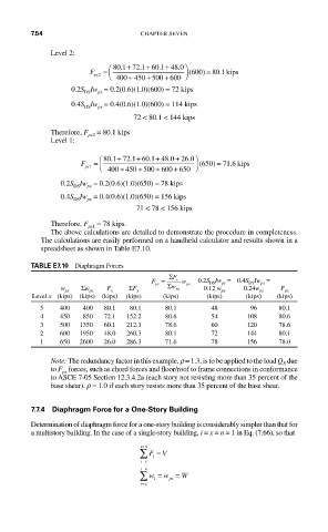
The above calculations are detailed to demonstrate the procedure in completeness.
The calculations are easily performed on a handheld calculator and results shown in a
spreadsheet as shown in Table E7.10.
TABLE E7.10 Diaphragm Forces
Σ
F px = F x w px 0.2S DS Iw px = 0.4S DS Iw px =
Σ
w px Σw px F x ΣF x w px 0.12 w px 0.24w px F px
Level x (kips) (kips) (kips) (kips) (kips) (kips) (kips) (kips)
5 400 400 80.1 80.1 80.1 48 96 80.1
4 450 850 72.1 152.2 80.6 54 108 80.6
3 500 1350 60.1 212.3 78.6 60 120 78.6
2 600 1950 48.0 260.3 80.1 72 144 80.1
1 650 2600 26.0 286.3 71.6 78 156 78.0
Note: The redundancy factor in this example, r = 1.3, is to be applied to the load Q due
E
to F forces, such as chord forces and floor/roof to frame connections in conformance
px
to ASCE 7-05 Section 12.3.4.2a (each story not resisting more than 35 percent of the
base shear). r = 1.0 if each story resists more than 35 percent of the base shear.
7.7.4 Diaphragm Force for a One-Story Building
Determination of diaphragm force for a one-story building is considerably simpler than that for
a multistory building. In the case of a single-story building, i = x = n = 1 in Eq. (7.66), so that
=
in
∑ F = V
i
=
ix
=
in
∑ w = w = W
i
px
=
ix