
Page 490 - Design of Reinforced Masonry Structures
P. 490
7.52 CHAPTER SEVEN
Design Category D, E, or F. For inertial forces calculated in accordance with Eq. (7.66),
the redundancy factor shall equal 1.0. For transfer forces, the redundancy factor shall be the
same as that used for the structure. For structures having horizontal or vertical structural
irregularities (of the types discussed in Section 7.8), the requirements indicated in AISC
7-05 Section 12.3.3.4 shall also apply.
7.7.3 Design Forces for Chords and Collector Elements
Shear walls receive their loads from horizontal diaphragms through connections between
the two elements. A shear wall supporting a diaphragm may be continuous running full
width of the diaphragm, or it may be discontinuous because of the presence of openings.
When the shear wall is discontinuous, collector elements (Fig. 7.22) are required to be
provided such that they are capable of transferring the seismic forces originating in other
portions of the structure to the element providing the resistance to those forces.
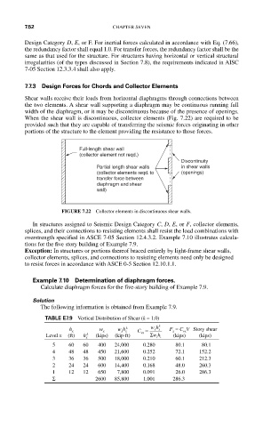
Full-length shear wall
(collector element not reqd.)
Discontinuity
Partial length shear walls in shear walls
(collector elements reqd. to (openings)
transfer force between
diaphragm and shear
wall)
FIGURE 7.22 Collector elements in discontinuous shear walls.
In structures assigned to Seismic Design Category C, D, E, or F, collector elements,
splices, and their connections to resisting elements shall resist the load combinations with
overstrength specified in ASCE 7-05 Section 12.4.3.2. Example 7.10 illustrates calcula-
tions for the five story building of Example 7.9.
Exception: In structures or portions thereof braced entirely by light-frame shear walls,
collector elements, splices, and connections to resisting elements need only be designed
to resist forces in accordance with ASCE 0-5 Section 12.10.1.1.
Example 7.10 Determination of diaphragm forces.
Calculate diaphragm forces for the five-story building of Example 7.9.
Solution
The following information is obtained from Example 7.9.
TABLE E7.9 Vertical Distribution of Shear (k = 1.0)
k wh k F x = C vx V Story shear
h x w x w x h x C vx = xx
Level x (ft) h x k (kips) (kip-ft) Σ wh (kips) (kips)
ii
5 60 60 400 24,000 0.280 80.1 80.1
4 48 48 450 21,600 0.252 72.1 152.2
3 36 36 500 18,000 0.210 60.1 212.3
2 24 24 600 14,400 0.168 48.0 260.3
1 12 12 650 7,800 0.091 26.0 286.3
Σ 2600 85,800 1.001 286.3