
Page 485 - Design of Reinforced Masonry Structures
P. 485
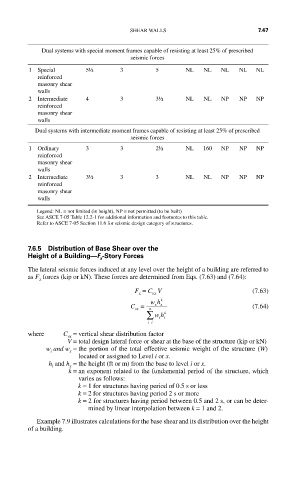
SHEAR WALLS                       7.47


            Dual systems with special moment frames capable of resisting at least 25% of prescribed
                                    seismic forces
         1  Special     5½       3         5       NL   NL  NL   NL   NL
           reinforced
           masonry shear
           walls
         2  Intermediate   4     3         3½      NL   NL  NP   NP   NP
           reinforced
           masonry shear
           walls
          Dual systems with intermediate moment frames capable of resisting at least 25% of prescribed
                                    seismic forces
         1  Ordinary    3        3         2½      NL   160  NP  NP   NP
           reinforced
           masonry shear
           walls
         2  Intermediate   3½    3         3       NL   NL  NP   NP   NP
           reinforced
           masonry shear
           walls
           Legend: NL = not limited (in height), NP = not permitted (to be built)
           See ASCE 7-05 Table 12.2-1 for additional information and footnotes to this table.
           Refer to ASCE 7-05 Section 11.6 for seismic design category of structures.


         7.6.5  Distribution of Base Shear over the
         Height of a Building—F -Story Forces
                            x
         The lateral seismic forces induced at any level over the height of a building are referred to
         as F  forces (kip or kN). These forces are determined from Eqs. (7.63) and (7.64):
            x
                                     F  = C  V                       (7.63)
                                      x   vx
                                    C =  wh k                        (7.64)
                                           xx
                                     vx  n
                                        ∑  wh  k
                                            ii
                                         ii =
         where    C = vertical shear distribution factor
                   vx
                   V =  total design lateral force or shear at the base of the structure (kip or kN)


             w  and w  =  the portion of the total effective seismic weight of the structure (W)
               i
                    x
                      located or assigned to Level i or x.
              h  and h  = the height (ft or m) from the base to level i or x.
               i
                    x

                   k =  an exponent related to the fundamental period of the structure, which
                      varies as follows:
                      k = 1 for structures having period of 0.5 s or less
                      k = 2 for structures having period 2 s or more
                      k =  2 for structures having period between 0.5 and 2 s, or can be deter-
                         mined by linear interpolation between k = 1 and 2.
           Example 7.9 illustrates calculations for the base shear and its distribution over the height
         of a building.