Page 483 - Design of Reinforced Masonry Structures
P. 483
SHEAR WALLS                       7.45

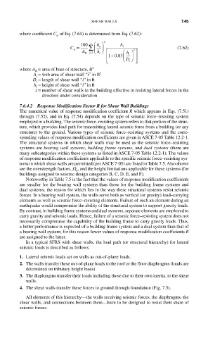
         where coefficient C  of Eq. (7.61) is determined from Eq. (7.62):
                       w
                                    x
                                       n
                            C =  100 ∑ ⎛ ⎜  h ⎞ ⎟  2  A i            (7.62)
                             w       ⎝  h ⎠ ⎡       2
                                A B  = i 1  i   ⎛  h ⎞ ⎤
                                           + 83
                                          ⎢10.  ⎜  i  ⎟  ⎥
                                          ⎢ ⎣   ⎝  D ⎠ ⎥ ⎦ ⎦
                                                  i
         where A  = area of base of structure, ft 2
              B
              A  = web area of shear wall “i” in ft 2
               i
              D  = length of shear wall “i” in ft
               i
              h  = height of shear wall “i” in ft
               i
              x =  number of shear walls in the building effective in resisting lateral forces in the
                 direction under consideration
         7.6.4.2  Response Modification Factor R for Shear Wall Buildings
         The numerical value of response modification coefficient R which appears in Eqs. (7.51)
         through (7.52), and in Eq. (7.54) depends on the type of seismic force–resisting system
         employed in a building. The seismic force–resisting system refers to that portion of the struc-
         ture, which provides load path for transmitting lateral seismic force from a building (or any
         structure) to the ground. Various types of seismic force–resisting systems and the corre-
         sponding values of response modification coefficients are given in ASCE 7-05 Table 12.2-1.
         The structural systems in which shear walls may be used as the seismic force–resisting
         systems are bearing wall systems, building frame systems, and dual systems (there are
         many subcategories within these systems as listed in ASCE 7-05 Table 12.2-1). The values
         of response modification coefficients applicable to the specific seismic force–resisting sys-
         tems in which shear walls are permitted (per ASCE 7-05) are listed in Table 7.5. Also shown
         are the overstrength factors, W , and the height limitations applicable for these systems (for
                              o
         buildings assigned to seismic design categories B, C, D, E, and F).
           Noteworthy in Table 7.5 is the fact that the values of response modification coefficients
         are smaller for the bearing wall systems than those for the building frame systems and
         dual systems; the reason for which lies in the way these structural systems resist seismic
         forces. In a bearing wall system, the walls serve both as vertical (or gravity) load–carrying
         elements as well as seismic force–resisting elements. Failure of such an element during an
         earthquake would compromise the ability of the structural system to support gravity loads.
         By contrast, in building frame systems and dual systems, separate elements are employed to
         carry gravity and seismic loads. Hence, failure of a seismic force–resisting system does not
         necessarily compromise the capability of the building frame to carry gravity loads. Thus,
         a better performance is expected of a building frame system and a dual system than that of
         a bearing wall system; for this reason lower values of response modification coefficients R
         are assigned to the latter.

           In a typical SFRS with shear walls, the load path (or structural hierarchy) for lateral
         seismic loads is described as follows:
         1. Lateral seismic loads act on walls as out-of-plane loads.
         2. The walls transfer these out-of-plane loads to the roof or the floor diaphragms (loads are
           determined on tributary height basis).
         3. The diaphragms transfer their loads including those due to their own inertia, to the shear
           walls.
         4. The shear walls transfer these forces to ground through foundation (Fig. 7.5).
           All elements of this hierarchy—the walls receiving seismic forces, the diaphragms, the
         shear walls, and connections between them—have to be designed to resist their share of
         seismic forces.

