
Page 488 - Design of Reinforced Masonry Structures
P. 488
7.50 CHAPTER SEVEN
For the example building, T = 0.43 s < 0.5 s, therefore, k = 1 so that
wh
C = xx
vx
∑ n wh
ii
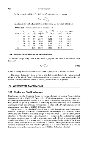
Calculations for vertical distribution of base shear are shown in Table E7.9.
TABLE E7.9 Vertical Distribution of Shear (k = 1.0)
k wh k F x = C vx V Story shear
h x w x w x h x C vx = xx
Level x (ft) h x k (kips) (kip-ft) Σ wh (kips) (kips)
ii
5 60 60 400 24,000 0.280 80.1 80.1
4 48 48 450 21,600 0.252 72.1 152.2
3 36 36 500 18,000 0.210 60.1 212.3
2 24 24 600 14,400 0.168 48.0 260.3
1 12 12 650 7,800 0.091 26.0 286.3
Σ 2600 85,800 1.001 286.3
7.6.6 Horizontal Distribution of Seismic Forces
The seismic design story shear in any story, V (kip or kN), shall be determined from
x
Eq. (7.65):
n
V = ∑ F (7.65)
x i
=
ix
where F = the portion of the seismic base shear (V ) (kip or kN) induced at Level i.
i x
The seismic design story shear, V (kip or kN), shall be distributed to the various vertical
x
elements of the seismic force–resisting system in the story under consideration based on the
relative lateral stiffness of the vertical resisting elements and the diaphragm.
7.7 HORIZONTAL DIAPHRAGMS
7.7.1 Flexible and Rigid Diaphragms
Diaphragms transfer horizontal forces to vertical elements of seismic force–resisting
systems as listed in ASCE 7-05 Table 12.2.1. While diaphragms can also be sloped, the
discussion presented herein pertains to floors and roof of buildings or building-like struc-
tures, which are generally horizontal. In a building, both roof and floors act as horizontal
diaphragms which transfer lateral seismic forces to shear walls. Design requirements for
diaphragms are specified in ASCE 7-05 Section 12.3.
Diaphragms are typically classified as flexible or rigid, depending on how they are con-
structed. Diaphragms constructed from untopped steel decking or wood structural panels
are usually (and permitted as such by design codes) considered as flexible diaphragms in
structures in which the vertical elements are steel or composite steel and concrete braced
frames or concrete, masonry, steel, or composite shear walls. Diaphragms constructed of
wood structural panels or untopped steel decks in one- or two-family residential buildings
of light frame construction are also considered as flexible. Diaphragms of concrete slab or
concrete-filled metal deck with span-to-depth ratio of 3 or less in structures that have no
horizontal irregularities are considered as rigid (ASCE 7-05 Section 12.3.1.2).