
Page 489 - Design of Reinforced Masonry Structures
P. 489
SHEAR WALLS 7.51
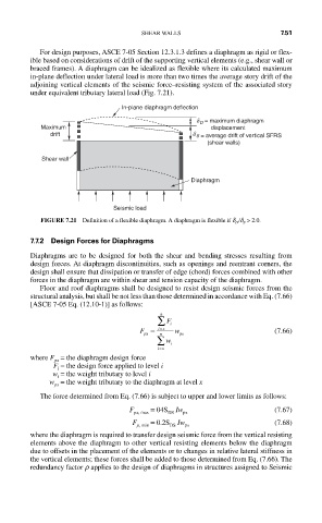
For design purposes, ASCE 7-05 Section 12.3.1.3 defines a diaphragm as rigid or flex-
ible based on considerations of drift of the supporting vertical elements (e.g., shear wall or
braced frames). A diaphragm can be idealized as flexible where its calculated maximum
in-plane deflection under lateral load is more than two times the average story drift of the
adjoining vertical elements of the seismic force–resisting system of the associated story
under equivalent tributary lateral load (Fig. 7.21).
In-plane diaphragm deflection
d D = maximum diaphragm
Maximum displacement
drift d S = average drift of vertical SFRS
(shear walls)
Shear wall
Diaphragm
Seismic load
FIGURE 7.21 Definition of a flexible diaphragm. A diaphragm is flexible if d D /d S > 2.0.
7.7.2 Design Forces for Diaphragms
Diaphragms are to be designed for both the shear and bending stresses resulting from
design forces. At diaphragm discontinuities, such as openings and reentrant corners, the
design shall ensure that dissipation or transfer of edge (chord) forces combined with other
forces in the diaphragm are within shear and tension capacity of the diaphragm.
Floor and roof diaphragms shall be designed to resist design seismic forces from the
structural analysis, but shall be not less than those determined in accordance with Eq. (7.66)
[ASCE 7-05 Eq. (12.10-1)] as follows:
n
∑ F i
=
F = ix w (7.66)
px
px
n
∑ w i
=
ix
where F = the diaphragm design force
px
F = the design force applied to level i
i
w = the weight tributary to level i
i
w = the weight tributary to the diaphragm at level x
px
The force determined from Eq. (7.66) is subject to upper and lower limits as follows:
F px, max = 04S Iw (7.67)
DS
px
F = 0.2S Iw (7.68)
p, min DS px
where the diaphragm is required to transfer design seismic force from the vertical resisting
elements above the diaphragm to other vertical resisting elements below the diaphragm
due to offsets in the placement of the elements or to changes in relative lateral stiffness in
the vertical elements; these forces shall be added to those determined from Eq. (7.66). The
redundancy factor r applies to the design of diaphragms in structures assigned to Seismic