
Page 115 - Design of Simple and Robust Process Plants
P. 115
100 Chapter 4 Process Synthesis and Design Optimization
4.2.2
Separation
The development of a separation train for a continuous process is divided into three
steps:
1. Selection of separation techniques.
2. Sequencing of separation techniques.
3. Adapting process conditions for integration and optimization.
The objective is to develop an elementary overall flowsheet that carefully shows
which components need to be removed, and where they are expected to leave the
process. The development steps will be discussed in order, although initially the
overall task of separation section needs to be defined by what is known as the
Douglas input and output structure of the flowsheet.
4.2.2.1 Develop an input and output process stream diagram
The input required for the stream diagram is a detailed component analysis of all
feed streams (including all additives) and of the reactor(s) inlet and outlet streams.
The stream diagram must contain external streams with quantitative and if not yet
available qualitative component information, and also show the major recycle
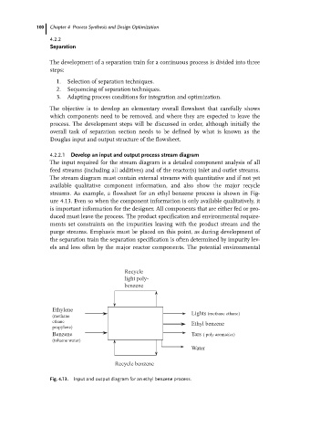
streams. As example, a flowsheet for an ethyl benzene process is shown in Fig-
ure 4.13. Even so when the component information is only available qualitatively, it
is important information for the designer. All components that are either fed or pro-
duced must leave the process. The product specification and environmental require-
ments set constraints on the impurities leaving with the product stream and the
purge streams. Emphasis must be placed on this point, as during development of
the separation train the separation specification is often determined by impurity lev-
els and less often by the major reactor components. The potential environmental
Recycle
light poly-
benzene
Ethylene
Lights (methane ethane)
(methane
ethane Ethyl benzene
propylene)
Benzene Tars ( poly aromatics)
(toluene water)
Water
Recycle benzene
Fig. 4.13. Input and output diagram for an ethyl benzene process.