
Page 125 - Design of Simple and Robust Process Plants
P. 125
110 Chapter 4 Process Synthesis and Design Optimization
Extraction followed by a distillation separations is another opportunity for
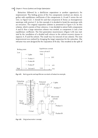
improvement. The boiling points of the five components involved are shown, to-
gether with equilibrium coefficients of the components A, B and P versus the sol-
vent, in Figure 4.21. It should be said that component B forms an homogeneous
azeotrope with product P. In this example it is decided to break the azeotrope with
an extraction. The original separation scheme is presented in Figure 4.22. In this
scheme, which consists of four columns, it was decided to extract both components
A and B; thus a large extraction column was needed, as component A had a low
equilibrium coefficient. The first generation improvement (Figure 4.23) was real-
ized by the installation of a divided wall column in the solvent recovery stream to
separate A, B and the solvent. The result was the removal of one column. The next
improvement was realized by changing the target separation for the extraction. The
extractor was now designed for the separation of B only. This resulted in the split of
Equilibrium constant
Boiling points
versus solvent S
Low
Lights High
B/S
Product A
Product B
Product P A/S
High Solvent S Low P/S
Fig. 4.21. Boiling points and equilibrium constants of extraction example.
Fig. 4.22. Original extraction concept.