
Page 121 - Design of Simple and Robust Process Plants
P. 121
106 Chapter 4 Process Synthesis and Design Optimization
Liquid recycle
Gas recycle Gas
Purge
separator
Vapor Liquid
recov. separ. Products
Byproducts
Reaction Flash Filter Decant.
Feeds
Dissolve Solid Liquid Products
recov. separ. Byproducts
Products
Byproducts
Solid
separ.
Solvent recycle
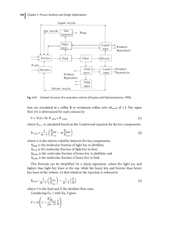
Fig. 4.15. General structure of a separation section (Douglas and Stephanopoulos, 1995).
tion are simulated at a reflux R to minimum reflux ratio (R min ) of 1.1 The vapor
flow (V) is determined for each column by
(1)
V= D (1+ R/ R min R min)
where R min is calculated based on the Underwood equation for the key components:
1 X X
R min = DLK a DHK (2)
a 1 X X
FLK FHK
where a is the relative volatility between the key components;
X DLK is the molecular fraction of light key in distillate;
X FLK is the molecular fraction of light key in feed;
X DHK is the molecular fraction of heavy key in distillate; and
X FHK is the molecular fraction of heavy key in feed.
This formula can be simplified for a sharp separation, where the light key and
lighter than light key leave at the top, while the heavy key and heavier than heavy
key leave at the bottom. In that situation the equation is reduced to
1 X 1
F
R min = a 1 DLK (3)
X
FLK a 1 D
where F is the feed and D the distillate flow rates.
Combining Eq. 1 with Eq. 2 gives
.
0 1
R R min F
V= D 1 A
@
a 1 D