
Page 316 - Design of Simple and Robust Process Plants
P. 316
302 Chapter 8 Instrumentation, Automation of Operation and Control
± z is axial reactor position
± a 1 decrease rate parameter for reactor inlet temperature
± a 2 increase parameter for flow rate
± u i is total reactor flow rate
± C B is concentration of reactant B
± w B is concentration of reactant B at the reactor inlet
± m h is the trajectory of the inlet temperature over time
± r is time
± h is temperature
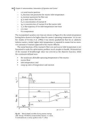
The manipulated variables over time are shown in Figure 8.5, the initial temperature
having been chosen to be higher than the normal operating temperature. In the ear-
lier studies of Verwijs et al. (1992) it was shown qualitatively that for an adiabatic
tubular reactor a initial higher inlet temperature is required to ensure that no exces-
sive amounts of reactant appeared in the reactor effluent.
The ramp functions of the reactant's flow rate and reactor inlet temperature a are
linearized to make the optimization problem much simpler to handle. Minimization
of the reactant B breakthrough value was selected as the objective function, while
the constraints defined were:
. the maximum allowable operating temperature of the reactor;
. reactor flow;
. inlet temperature; and
. ramp-up rates of temperature and reactant.
Fig. 8.5. Manipulated variables during reactor startup
(Ref. Verwijs '95 AIChE) dimensionless factors: r is time,
h is temperature, a ramp up/down rate, F is flow.