
Page 236 - Design of Solar Thermal Power Plants
P. 236
3.9 MAIN POINTS FOR POWER PLANT SITE PLAN 219
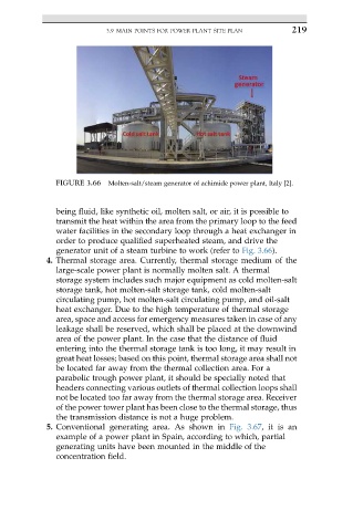
FIGURE 3.66 Molten-salt/steam generator of achimide power plant, Italy [2].
being fluid, like synthetic oil, molten salt, or air, it is possible to
transmit the heat within the area from the primary loop to the feed
water facilities in the secondary loop through a heat exchanger in
order to produce qualified superheated steam, and drive the
generator unit of a steam turbine to work (refer to Fig. 3.66).
4. Thermal storage area. Currently, thermal storage medium of the
large-scale power plant is normally molten salt. A thermal
storage system includes such major equipment as cold molten-salt
storage tank, hot molten-salt storage tank, cold molten-salt
circulating pump, hot molten-salt circulating pump, and oil-salt
heat exchanger. Due to the high temperature of thermal storage
area, space and access for emergency measures taken in case of any
leakage shall be reserved, which shall be placed at the downwind
area of the power plant. In the case that the distance of fluid
entering into the thermal storage tank is too long, it may result in
great heat losses; based on this point, thermal storage area shall not
be located far away from the thermal collection area. For a
parabolic trough power plant, it should be specially noted that
headers connecting various outlets of thermal collection loops shall
not be located too far away from the thermal storage area. Receiver
of the power tower plant has been close to the thermal storage, thus
the transmission distance is not a huge problem.
5. Conventional generating area. As shown in Fig. 3.67,itisan
example of a power plant in Spain, according to which, partial
generating units have been mounted in the middle of the
concentration field.