
Page 246 - Design of Solar Thermal Power Plants
P. 246
4.2 PRINCIPLES FOR CONCENTRATION FIELD LAYOUT 229
0° Mean value 45° Mean value 90° Mean value 180° Mean value
100
90
Mean reflectivity /% 70
80
60
50
40
30
20
10
Nov. 26 th , 2011
Aug. 28 th , 2011 Sept. 27 th , 2011 Oct. 12 th , 2011 Oct. 27 th , 2011 Nov. 11 th , 2011 Dec. 11 th , 2011 Dec. 26 th , 2011 Jan. 10 th , 2012 Jan. 25 th , 2012 Feb. 9 th , 2012 Feb. 24 th , 2012 Mar. 10 th , 2012 Mar. 25 th , 2012 Apr. 9 th , 2012 Apr. 24 th , 2012 May 9 th , 2012 May 24 th , 2012 Date
Sept. 12 th , 2011
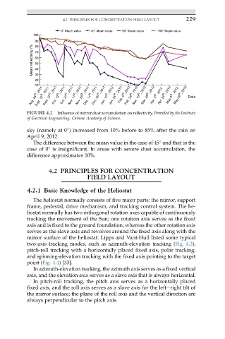
FIGURE 4.2 Influence of mirror dust accumulation on reflectivity. Provided by the Institute
of Electrical Engineering, Chinese Academy of Science.
sky (namely at 0 ) increased from 10% before to 85% after the rain on
April 9, 2012.
The difference between the mean value in the case of 45 and that in the
case of 0 is insignificant. In areas with severe dust accumulation, the
difference approximates 10%.
4.2 PRINCIPLES FOR CONCENTRATION
FIELD LAYOUT
4.2.1 Basic Knowledge of the Heliostat
The heliostat normally consists of five major parts: the mirror, support
frame, pedestal, drive mechanism, and tracking control system. The he-
liostat normally has two orthogonal rotation axes capable of continuously
tracking the movement of the Sun; one rotation axis serves as the fixed
axis and is fixed to the ground foundation, whereas the other rotation axis
serves as the slave axis and revolves around the fixed axis along with the
mirror surface of the heliostat. Lipps and Vant-Hull listed some typical
two-axis tracking modes, such as azimuth-elevation tracking (Fig. 4.3),
pitch-roll tracking with a horizontally placed fixed axis, polar tracking,
and spinning-elevation tracking with the fixed axis pointing to the target
point (Fig. 4.4) [33].
In azimuth-elevation tracking, the azimuth axis serves as a fixed vertical
axis, and the elevation axis serves as a slave axis that is always horizontal.
In pitch-roll tracking, the pitch axis serves as a horizontally placed
fixed axis, and the roll axis serves as a slave axis for the lefteright tilt of
the mirror surface; the plane of the roll axis and the vertical direction are
always perpendicular to the pitch axis.