
Page 248 - Design of Solar Thermal Power Plants
P. 248
4.2 PRINCIPLES FOR CONCENTRATION FIELD LAYOUT 231
perpendicular to the spin axis (Fig. 4.4). The elevation axis is fixed along
the sagittal direction of the mirror surface on the support frame of the
heliostat and revolves around the spinning axis together with the frame
and the mirror surface.
The azimuth-elevation tracking mode is the most common two-axis
tracking mode and is applied by most solar trackers, parabolic solar
dish concentrators, and heliostats. Analysis by Schramek and Mills
concluded that compared with azimuth-elevation tracking, pitch-roll
tracking is capable of making the heliostat field layout more compact.
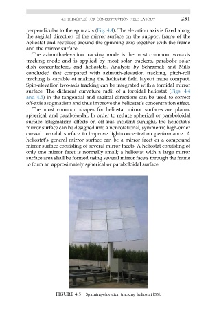
Spin-elevation two-axis tracking can be integrated with a toroidal mirror
surface. The different curvature radii of a toroidal heliostat (Figs. 4.4
and 4.5) in the tangential and sagittal directions can be used to correct
off-axis astigmatism and thus improve the heliostat’s concentration effect.
The most common shapes for heliostat mirror surfaces are planar,
spherical, and paraboloidal. In order to reduce spherical or paraboloidal
surface astigmatism effects on off-axis incident sunlight, the heliostat’s
mirror surface can be designed into a nonrotational, symmetric high-order
curved toroidal surface to improve light-concentration performance. A
heliostat’s general mirror surface can be a mirror facet or a compound
mirror surface consisting of several mirror facets. A heliostat consisting of
only one mirror facet is normally small; a heliostat with a large mirror
surface area shall be formed using several mirror facets through the frame
to form an approximately spherical or paraboloidal surface.
FIGURE 4.5 Spinning-elevation tracking heliostat [33].