Page 269 - Design of Solar Thermal Power Plants
P. 269

4.3 DESIGN OF THE SOLAR TOWER POWER PLANT     251

                     Tower

                                                                      X
                                           R m+1
                                       R m


                                                 (m--1,n+1) min

                                                θ       (m--1,n+1) max
                ΔR min
                                                        θ

                         θ (m+1,n) min


                           θ (m+1,n) max


                     -y
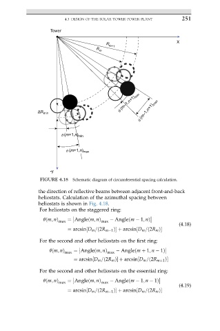
                 FIGURE 4.18  Schematic diagram of circumferential spacing calculation.

                the direction of reflective beams between adjacent front-and-back
                heliostats. Calculation of the azimuthal spacing between
                heliostats is shown in Fig. 4.18.
                For heliostats on the staggered ring:

                  qðm; nÞ max  ¼ Angleðm; nÞ max    Angleðm   1; nÞ

                                                                       (4.18)
                           ¼ arcsin½D m =ð2R m 1 ފ þ arcsin½D m =ð2R m ފ
                For the second and other heliostats on the first ring:


                    qðm; nÞ max  ¼ Angleðm; nÞ max    Angleðm þ 1; n   1Þ

                              ¼ arcsin½D m =ð2R m ފ þ arcsin½D m =ð2R mþ1 ފ
                 For the second and other heliostats on the essential ring:

                  qðm; nÞ  ¼ Angleðm; nÞ      Angleðm   1; n   1Þ
                        max              max

                                                                       (4.19)
                           ¼ arcsin½D m =ð2R m 1 ފ þ arcsin½D m =ð2R m ފ
   264   265   266   267   268   269   270   271   272   273   274