
Page 270 - Design of Solar Thermal Power Plants
P. 270
252 4. DESIGN OF THE CONCENTRATION SYSTEM
Thus during optimization design, the azimuthal positions of the
heliostat can be calculated through the following equation:
Angleðm; nÞ¼ Angleðm; nÞ þ A min max qðm; nÞ qðm; nÞ ;
min max min
0 < A min max < 1
(4.20)
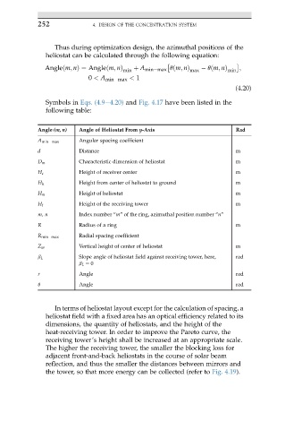
Symbols in Eqs. (4.9e4.20) and Fig. 4.17 have been listed in the
following table:
Angle (m, n) Angle of Heliostat From y-Axis Rad
A min max Angular spacing coefficient
d Distance m
D m Characteristic dimension of heliostat m
H c Height of receiver center m
H h Height from center of heliostat to ground m
H m Height of heliostat m
H t Height of the receiving tower m
m, n Index number “m” of the ring, azimuthal position number “n”
R Radius of a ring m
R min max Radial spacing coefficient
Z m Vertical height of center of heliostat m
b L Slope angle of heliostat field against receiving tower, here, rad
b L ¼ 0
r Angle rad
q Angle rad
In terms of heliostat layout except for the calculation of spacing, a
heliostat field with a fixed area has an optical efficiency related to its
dimensions, the quantity of heliostats, and the height of the
heat-receiving tower. In order to improve the Pareto curve, the
receiving tower’s height shall be increased at an appropriate scale.
The higher the receiving tower, the smaller the blocking loss for
adjacent front-and-back heliostats in the course of solar beam
reflection, and thus the smaller the distances between mirrors and
the tower, so that more energy can be collected (refer to Fig. 4.19).