
Page 283 - Design of Solar Thermal Power Plants
P. 283
4.5 SOLAR FIELD DESIGN OF PARABOLIC TROUGH POWER PLANT 265
(A) Z
Y North
θ
α s
West East
γ
s
Y
South
North-south horizontal-axis tracking
(B) Z East
Y
θ
α s
γ s
North South
Y
West
West-east horizontal-axis tracking
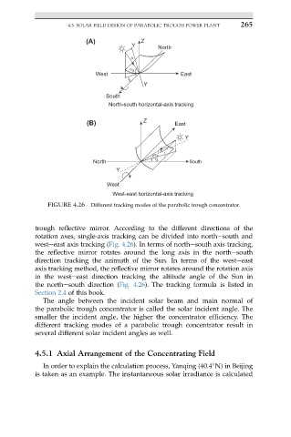
FIGURE 4.26 Different tracking modes of the parabolic trough concentrator.
trough reflective mirror. According to the different directions of the
rotation axes, single-axis tracking can be divided into northesouth and
westeeast axis tracking (Fig. 4.26). In terms of northesouth axis tracking,
the reflective mirror rotates around the long axis in the northesouth
direction tracking the azimuth of the Sun. In terms of the westeeast
axis tracking method, the reflective mirror rotates around the rotation axis
in the westeeast direction tracking the altitude angle of the Sun in
the northesouth direction (Fig. 4.26). The tracking formula is listed in
Section 2.4 of this book.
The angle between the incident solar beam and main normal of
the parabolic trough concentrator is called the solar incident angle. The
smaller the incident angle, the higher the concentrator efficiency. The
different tracking modes of a parabolic trough concentrator result in
several different solar incident angles as well.
4.5.1 Axial Arrangement of the Concentrating Field
In order to explain the calculation process, Yanqing (40.4 N) in Beijing
is taken as an example. The instantaneous solar irradiance is calculated