
Page 107 - Designing Autonomous Mobile Robots : Inside the Mindo f an Intellegent Machine
P. 107
Chapter 6
802.11 802.11 Ethernet Video
Ethernet Ethernet Camera
Access Point Radio Server
Port Slave 2 Xducers
Server (Sonar)
Ethernet Access Point Supervisor Slave 3 Ranger
802.11
Laser
Ethernet
(Lidar)
RS-232 Control
Slave 1
Mobile Base
RS-232
Host
Computer Master
Mobile Base
Mobile Robot
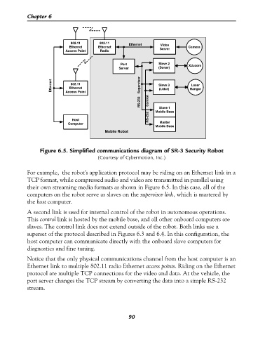
Figure 6.5. Simplified communications diagram of SR-3 Security Robot
(Courtesy of Cybermotion, Inc.)
For example, the robot’s application protocol may be riding on an Ethernet link in a
TCP format, while compressed audio and video are transmitted in parallel using
their own streaming media formats as shown in Figure 6.5. In this case, all of the
computers on the robot serve as slaves on the supervisor link, which is mastered by
the host computer.
A second link is used for internal control of the robot in autonomous operations.
This control link is hosted by the mobile base, and all other onboard computers are
slaves. The control link does not extend outside of the robot. Both links use a
superset of the protocol described in Figures 6.3 and 6.4. In this configuration, the
host computer can communicate directly with the onboard slave computers for
diagnostics and fine tuning.
Notice that the only physical communications channel from the host computer is an
Ethernet link to multiple 802.11 radio Ethernet access points. Riding on the Ethernet
protocol are multiple TCP connections for the video and data. At the vehicle, the
port server changes the TCP stream by converting the data into a simple RS-232
stream.
90