
Page 129 - Designing Autonomous Mobile Robots : Inside the Mindo f an Intellegent Machine
P. 129
Chapter 7
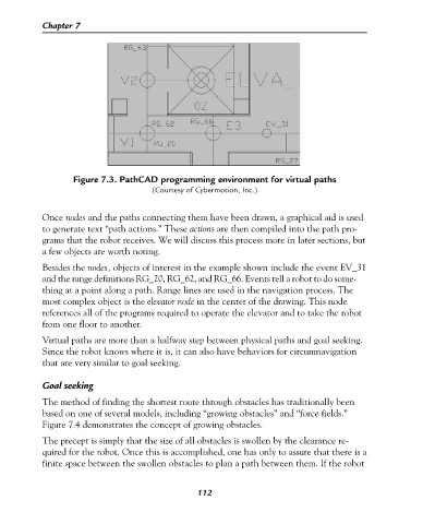
Figure 7.3. PathCAD programming environment for virtual paths
(Courtesy of Cybermotion, Inc.)
Once nodes and the paths connecting them have been drawn, a graphical aid is used
to generate text “path actions.” These actions are then compiled into the path pro-
grams that the robot receives. We will discuss this process more in later sections, but
a few objects are worth noting.
Besides the nodes, objects of interest in the example shown include the event EV_31
and the range definitions RG_20, RG_62, and RG_66. Events tell a robot to do some-
thing at a point along a path. Range lines are used in the navigation process. The
most complex object is the elevator node in the center of the drawing. This node
references all of the programs required to operate the elevator and to take the robot
from one floor to another.
Virtual paths are more than a halfway step between physical paths and goal seeking.
Since the robot knows where it is, it can also have behaviors for circumnavigation
that are very similar to goal seeking.
Goal seeking
The method of finding the shortest route through obstacles has traditionally been
based on one of several models, including “growing obstacles” and “force fields.”
Figure 7.4 demonstrates the concept of growing obstacles.
The precept is simply that the size of all obstacles is swollen by the clearance re-
quired for the robot. Once this is accomplished, one has only to assure that there is a
finite space between the swollen obstacles to plan a path between them. If the robot
112