
Page 233 - Designing Autonomous Mobile Robots : Inside the Mindo f an Intellegent Machine
P. 233
Chapter 14
Flashback…
This story is a prequel to the story in Chapter 6. A few years before the first practical lidar
systems were introduced, we were working with a Navy group to find ways to navigate
rack warehouses. It quickly became apparent that the posts of the racks were among the
only dependable features from which to navigate. The problem was that there was too
much clutter in the area of these posts to depend on imaging them by themselves. We
then decided that we would decorate the posts by mounting reflective tape on them, and
navigate from this easily discriminated artificial feature (called a fiducial).
The problem at the time was that the only affordable sensors were optical readers that
would close a circuit when their beams detected a retroreflector. Since the readers re-
turned no range information, it was necessary to imply position information from multiple
robot time-places.
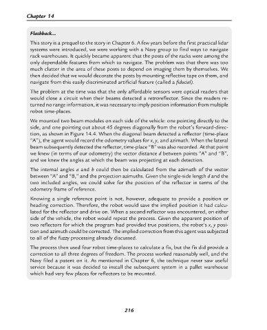
We mounted two beam modules on each side of the vehicle: one pointing directly to the
side, and one pointing out about 45 degrees diagonally from the robot’s forward-direc-
tion, as shown in Figure 14.4. When the diagonal beam detected a reflector (time-place
“A”), the agent would record the odometry values for x, y, and azimuth. When the lateral
beam subsequently detected the reflector, time-place “B” was also recorded. At that point
we knew (in terms of our odometry) the vector distance d between points “A” and “B”,
and we knew the angles at which the beam was projecting at each detection.
The internal angles a and b could then be calculated from the azimuth of the vector
between “A” and “B,” and the projection azimuths. Given the single-side length d and the
two included angles, we could solve for the position of the reflector in terms of the
odometry frame of reference.
Knowing a single reference point is not, however, adequate to provide a position or
heading correction. Therefore, the robot would save the implied position it had calcu-
lated for the reflector and drive on. When a second reflector was encountered, on either
side of the vehicle, the robot would repeat the process. Given the apparent position of
two reflectors for which the program had provided true positions, the robot’s x, y posi-
tion and azimuth could be corrected. The implied correction from this agent was subjected
to all of the fuzzy processing already discussed.
The process then used four robot time-places to calculate a fix, but the fix did provide a
correction to all three degrees of freedom. The process worked reasonably well, and the
Navy filed a patent on it. As mentioned in Chapter 6, the technique never saw useful
service because it was decided to install the subsequent system in a pallet warehouse
which had very few places for reflectors to be mounted.
216