Page 182 - Digital Analysis of Remotely Sensed Imagery
P. 182

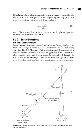
Image Geometric Rectification      147

               Calculation of this distortion requires measurement of the radial dis-
               tance r from the principal point of the photograph [Eq. (5.3)]. The
               distortion on the photography Δr is calculated as


                                      Δ=   Hr 3                      (5.3)
                                        r
                                           2 Rf  2
               where f is focal length of the camera used to take the photograph, and
               H and R are as defined previously.

               5.1.2 Sensor Distortions
               Off-Nadir Scale Distortion
               Scan-direction distortion is caused by the nonuniformity in object dis-
               tance, while image distance (e.g., focal length) remains constant during
               scanning (Fig. 5.4). This type of distortion is especially pronounced in
               airborne thermal infrared and radar imagery which is acquired at a
               close range to the ground. During a scan, the scene directly beneath the
               scanner has the shortest object distance. As the scanning mirror rotates
               away from this nadir position the object distance becomes increasingly

                                                            Δy
                                                              f    Δy
                                                                f
                                                            O


                                                         q
                                                    Scan angle
                                                                     H o
                                 o
                             A
                            H  = H  secq                    Δq
                                             Δq = instantaneous
                                                field-of-view

                      Δq H secq

                        C

                            A
                        ΔY                             Area covered by
                   Area covered by                     the scan spot
                   the scan spot
               FIGURE 5.4  Tangential scale distortion caused by changing object distance
               during scanning.
   177   178   179   180   181   182   183   184   185   186   187