
Page 262 - Digital Analysis of Remotely Sensed Imagery
P. 262
224 Cha pte r S i x
5 8 10 5 8 10
7 16 9 7 8 9
6 5 11 6 5 11
(a) (b)
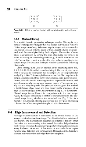
FIGURE 6.14 Effect of median fi ltering. (a) Input window; (b) median-fi ltered
output.
6.3.4 Median Filtering
As a spatial domain processing technique, median filtering is very
similar to image smoothing in that it is carried out within a window.
Unlike image smoothing, it does not require an operant, or a convolu-
tion kernel. Instead, only the pixels within a neighborhood are exam-
ined, with the central pixel being the focal point. The median of these
pixels is determined by sorting the nine DNs inside the window in
either ascending or descending order (e.g., the fifth number in the
list). This median is used to replace the pixel value in question in the
output image. For instance, the input window contains the following
nine pixels:
After sorting, their DNs are ordered in the ascending order of 5,
5, 6, 7, 8, 9, 10, 11, 16, with the median being 8. The central pixel value
of 16 is replaced by the median 8 as the output DN for the pixel under
study (Fig. 6.14b). This example illustrates that this filter requires only
simple calculation and thus can be implemented very quickly. Never-
theless, it is effective in removing outliers, impulse-like noises, and
speckles commonly encountered in radar imagery. These noises usu-
ally occur as singular pixels. The principal advantage of this method
is that it leaves edges intact and thus preserves the sharpness of an
edge (Richards and Jia, 2006). As illustrated in Fig. 6.13d, the median-
filtered image is also blurred in comparison with the raw image.
Again, the degree of blurring is related to the template size. The pro-
cessed image is very similar to the smoothed one (Fig. 6.13b). As a
matter of fact, median filtering degenerates into low-pass smoothing
if the median of the nine pixels is replaced with their mean.
6.4 Edge Enhancement and Detection
An edge or linear feature is manifested as an abrupt change in DN
along a certain direction in an image. This direction is the orientation of
that feature. The manifestation becomes an extreme of the first-order
derivative or a zero crossing in the second derivative. Edge detection
can be based on such a discontinuity property by tracing the maximum
along the bound of an area. A few methods are available for imple-
menting edge detection and enhancement. This section introduces two
of them, self-subtraction and edge-detection templates.