
Page 264 - Digital Analysis of Remotely Sensed Imagery
P. 264
226 Cha pte r S i x
duplicating the border rows and columns. However, those linear fea-
tures very close to the image border cannot be detected well using
this method.
The above discussion applies to ideal situations where there is
no noise in the image, which is rarely true in reality. In order to reduce
the random variation of pixels within the same feature and hence
improve the reliability of edge detection, it may be necessary to smooth
the image using the methods described in Sec. 6.3.3 before it is used in
the detection. The detection quality can also be improved by imposing
a threshold to test the validity of the detected edges in a postdetection
session. For instance, only those differences exceeding a certain thresh-
old are regarded as representing genuine edges. All other differences
are treated as noise and removed. Another postdetection process-
ing technique is to spatially filter the detected results. All isolated non-
zero pixels that do not appear to be aligned with any linear segments
in a meaningful direction are eliminated from the output image.
6.4.2 Edge-Detection Templates
Several templates have been devised for edge detection (Fig. 6.16).
All of them have one characteristic in common: the sum of all ele-
ments in a kernel is zero. These zero-sum kernels smooth out areas of
low spatial frequency (e.g., absence of any edge), and cause a low
output in areas of low spatial frequency. In areas of high spatial fre-
quency (e.g., the interface of homogeneous patches of pixels), a sharp
contrast results. It is possible for the edge-enhanced images to con-
tain only edges and zeros. In areas of high spatial frequency, the dis-
parity among pixel values is magnified as large values become larger
while low values become even lower owing to the unequal element
values along the first/last row/column (Leica, 2006). Edges are
enhanced in the filtered image as it frequently is made up of only
edges and zeros.
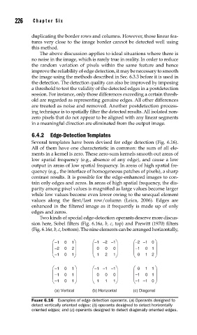
Two kinds of special edge-detection operants deserve more discus-
sion here, Sobel filters (Fig. 6.16a, b, c, top) and Prewitt (1970) filters
(Fig. 6.16a, b, c, bottom). The nine elements can be arranged horizontally,
–1 0 1 –1 –2 –1 –2 –1 0
–2 0 2 0 0 0 –1 0 1
–1 0 1 1 2 1 0 1 2
–1 0 1 –1 –1 –1 0 1 1
–1 0 1 0 0 0 –1 0 1
–1 0 1 1 1 1 –1 –1 0
(a) Vertical (b) Horizontal (c) Diagonal
FIGURE 6.16 Examples of edge detection operants. (a) Operants designed to
detect vertically oriented edges; (b) operants designed to detect horizontally
oriented edges; and (c) operants designed to detect diagonally oriented edges.