
Page 108 - Distillation theory
P. 108
P1: FCH/FFX P2: FCH/FFX QC: FCH/FFX T1: FCH
0521832772c04 CB644-Petlyuk-v1 June 11, 2004 17:49
82 Trajectories of Thermodynamically Reversible Distillation
1
C-2
1,2
C-1
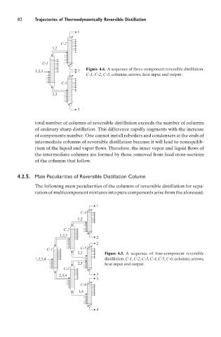
Figure 4.4. A sequence of three-component reversible distillation.
1,2,3 2
C-1, C-2, C-3, columns; arrows, heat input and output.
C-3
2,3
3
total number of columns of reversible distillation exceeds the number of columns
of ordinary sharp distillation. This difference rapidly augments with the increase
of components number. One cannot install reboilers and condensers at the ends of
intermediate columns of reversible distillation because it will lead to nonequilib-
rium of the liquid and vapor flows. Therefore, the inner vapor and liquid flows of
the intermediate columns are formed by those removed from feed cross-sections
of the columns that follow.
4.2.5. Main Peculiarities of Reversible Distillation Column
The following main peculiarities of the columns of reversible distillation for sepa-
ration of multicomponent mixtures into pure components arise from the aforesaid:
1
C-4
1,2
C-2
1,2,3
2
2
C-1 C-5
23 Figure 4.5. A sequence of four-component reversible
,
1,2,3,4 distillation. C-1, C-2, C-3, C-4, C-5, C-6, columns; arrows,
23 heat input and output.
,
C-3
2,3,4 3
3
C-6
3,4
4