
Page 109 - Distillation theory
P. 109
P1: FCH/FFX P2: FCH/FFX QC: FCH/FFX T1: FCH
0521832772c04 CB644-Petlyuk-v1 June 11, 2004 17:49
4.3 Trajectory Bundles of Sharp Reversible Distillation 83
1/K 3
3.0
2.8
x 2 x 1
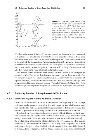
2.6 Figure 4.6. Liquid and vapor flow rate and
C-1 C-2 composition profiles of a three-component
2.4
reversible distillation. C-1, C-2, C-3, columns;
x 3 x 2
2.2 x 1 x 1 , x 2 , x 3 , concentrations of component 1, 2,
x 1 x 2
2.0 3 on columns trays; K 3 , vapor–liquid phase
x 3 equilibrium coefficient of component 3; thick
1.8 x 1 x 2 x 2
line, liquid flow rate profile; dotted line, va-
x 3
1.6 por flow rate profile; thin line, concentration
C-3
1.4 x 3 profile.
1.2 x 2
1.0 L,V, x
0 0.4 0.8 1.2 1.6 0 0.4 0.8 1.2 1.6
(1) all the columns are infinite; (2) one component is exhausted in each section of
each column; (3) infinitesimal amount of heat is brought to or drained from each
intermediate cross-section of each column; (4) liquid and vapor flows are created
at the ends of the intermediate (nonproduct) columns by removing these flows
from feed cross-sections of the columns that follow; and (5) liquid and vapor flows
are created at the ends of the product columns with the help of condensers and
reboilers with a finite value of output and input of heat.
The analysis of the reversible distillation of ideal mixtures has led to important
practical results. The use of flowsheets of the same type as those shown in Fig.
4.4 but consisting of real adiabatic columns (i.e., columns with finite numbers of
separation stages), without intermediate input of heat and cold and with product
columns joined into one complex column (Petlyuk, Platonov, & Slavinskii, 1965),
allows energy consumption for separation to be reduced by thirty to forty percent.
4.3. Trajectory Bundles of Sharp Reversible Distillation
4.3.1. Bundles and Regions of Sharp Reversible Distillation
Such a set of trajectories for which not more than one trajectory passes through
each nonsingular point is convenient for understanding as a distillation trajec-
tory bundle. This notion is different for various modes of distillation because the
number of parameters influencing the location of the trajectories is different.
It is clear from Fig. 4.1 that the location of a reversible distillation section trajec-
tory is determined only by the location of its product point (i.e., it does not depend
on any parameter). One component is absent at sharp reversible distillation [i.e.,
the product point of the section is located at some (n − 1) component edge, face, or
hyperface of the concentration simplex]. That is why, in all the points of a section
trajectory at sharp reversible distillation, liquid–vapor tie-lines should be directed
to this edge, face, or hyperface or from it [i.e., one and the same component should