
Page 335 - Dust Explosions in the Process Industries
P. 335
304 Dust Explosions in the Process Industries
This argument may not be fully justified, but it is necessary to account for the fact that,
in any closed-bomb experiment, the unburned mixture starts to become compressed
right from the onset of flame propagation.
4.2.6.2
Experimental Determination of Minimum Explosible Dust Concentration
Selle and Zehr (1957) described a closed-bombmethod that utilized the flame propaga-
tion criterionof explosion.A sphericalglass bomb of volume 1.4 liters was used, in which
a given quantity of dust, placed in a small hemisphericalcup, was dispersed into a cloud
by means of a blast of compressed air and exposed to an ignition source at the sphere
center.The concentration of dust was gradually lowered in a series of consecutive exper-
iments until the flame no longer propagated throughout the entire volume of the bomb.
This means that Selle and Zehr had chosen the requirement of a fully developed flame
within the bomb as their criterion of explosion. The size of the flame was recorded on
photographicfilm, and this facilitated an objectivedecision of whether the flame had actu-
ally filled the entire volume of the bomb. Nevertheless, the explosion criterionitself was
the result of a subjective choice.
Selle and Zehr observed that flames that occupied only part of the bomb volume were
not necessarily located in the vicinity of the ignition source. Due to inhomogeneities in
the dust concentration throughout the volume of the explosion bomb, flame propagation
could be restricted to local, almost detached “pockets” in the dust cloud.
This kind of nonhomogeneous structure is an inherent feature of real dust flames in
general, which clearly complicates the interpretation of marginal flame propagation in
small-scaleapparatus in terms of minimumexplosibleconcentrationin large, industrial-scale
systems. Therefore, experiments have also been conducted in fairly large industrial-scale
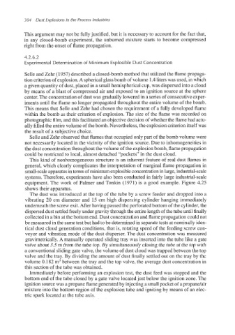
equipment. The work of Palmer and Tonkin (1971) is a good example. Figure 4.25
shows their apparatus.
The dust was introduced at the top of the tube by a screw feeder and dropped into a
vibrating 20 cm diameter and 15 cm high dispersing cylinder hanging immediately
underneath the screw exit. After having passed the perforated bottom of the cylinder, the
disperseddust settled freely under gravity through the entire length of the tube until finally
collected in a bin at the bottom end. Dust concentration and flame propagation could not
be measured in the same test but had to be determined in separatetests at nominally iden-
tical dust cloud generation conditions, that is, rotating speed of the feeding screw con-
veyor and vibration mode of the dust disperser. The dust concentration was measured
gravimetrically. A manually operated sliding tray was inserted into the tube like a gate
valve about 3.5 m from the tube top. By simultaneously closing the tube at the top with
a conventionalsliding gate valve, the volume of dust cloud was trapped between the top
valve and the tray. By dividing the amount of dust finally settled out on the tray by the
volume 0.182 m3between the tray and the top valve, the average dust concentration in
this section of the tube was obtained.
Immediately before performing an explosion test, the dust feed was stopped and the
bottom end of the tube closed by a gate valve located just below the ignition zone. The
ignition source was a propane flame generated by injectinga small pocket of a propane/air
mixture into the bottom region of the explosion tube and igniting by means of an elec-
tric spark located at the tube axis.