
Page 602 - Dust Explosions in the Process Industries
P. 602
Electrical Apparatuses for Areas Containing Combustible Dusts 569
coming in contact with electrical components in general, including components that
may generate electric sparks or hot surfaces. Hence, direct adoption of the entire con-
cept of “intrinsically safe design” from the gadvapor domain into the domain of com-
bustible dusts does not seem to be an optimal approach.
However, in some highly special applications, there is a genuine need for intrinsically
safe apparatus in environments containing combustible powders or dusts. One exam-
ple is capacitive level indicators for solid bulk materials stored in silos and bins. In this
case, a live capacitor “plate,” in the form of a bare metal rope carrying a voltage to
ground, is directly exposed to the combustible powder and dust inside the silo or bin.
According to Klotz-Engmann (private communication, 200 1, 2002), an ignition risk
could arise from electrical sparks generated by direct contact between the energized bare
metal rope and any grounded metal part of the silo. This possibility has to be consid-
ered in zones 20 and 21, at least when taking into account possible faults. Figure 8.6
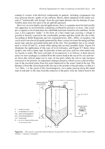
illustrates the application of this type of level indicator; and Figure 8.7 shows three
models, one with a metal rope, for powders in bins and silos, and two with metal rods,
for liquids in tanks. The basic principle of measurement is as follows: A short electric
pulse (ns wave package) is emitted from the sensor head at the top of the silo and trav-
els down the vertical metal rod or rope. At the point where the rod or rope becomes
immersed in the powder, its impedance changes abruptly, which causes a partial reflec-
tion of the electrical pulse from this point backward to the sensor head at the top. The
distance d from the sensor head at the silo top to the powder or liquid surface is then d =
l/zct. Here, c is the speed of the electromagnetic wave pulse passing along the metal
rope or rod and t is the time from the emission of the pulse from the sensor head to the
reference point of 9
measurement
..... ,---------
. ....
max. 20 m /67 ft
/
LN
remote display
FHX 40
F = measuring span
E = emptydistance (=zero)
UB = upper blocking distance
LB = lower blocking distance
LN = probe length
5 = minimumdistanceoftheprobe
to :hecontainerwali
Figure 8.6 The use ofa capacitive level indicator for powders in silos (Courtesy of C. Klotz-Engmann,
Endress + Hauser, Germany).