
Page 250 - Dynamic Loading and Design of Structures
P. 250
Page 221
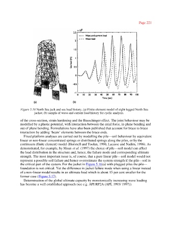
Figure 5.16 North Sea jack and sea load history, (a) Finite element model of eight-legged North Sea
jacket; (b) sample of wave and current load history for cyclic analysis.
of the cross-section, strain hardening and the Bauschinger effect. The joint behaviour may be
modelled by a plastic potential, with interaction between the axial force, in-plane bending and
out of plane bending. Formulations have also been published that account for brace to brace
interaction by adding ‘beam’ elements between the brace ends.
Fixed platform analyses are carried out by modelling the pile—soil behaviour by equivalent
linear or non-linear concentrated springs or distributed springs along the piles, or by the
continuum (finite element) model (Horsnell and Toolan, 1996; Lacasse and Nadim, 1996). As
demonstrated, for example, by Moan et al. (1997) the choice of pile—soil model can affect
the load distribution in the structure and, hence, the failure mode and corresponding ultimate
strength. The most important issue is, of course, that a pure linear pile—soil model would not
represent a possible soil failure and hence overestimate the system strength if the pile—soil is
the critical part of the system. For the jacket in Figure 5.16(a) with plugged piles the pile—
foundation is not critical. Yet the difference in jacket failure mode when using a linear instead
of a non-linear model results in an ultimate load which is about 15 per cent smaller for the
former case (Figure 5.17).
Determination of the global ultimate capacity by monotonically increasing wave loading
has become a well established approach (see e.g. API RP2A (API, 1993/ 1997)).