
Page 32 - Dynamic Loading and Design of Structures
P. 32
Page 19
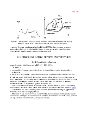
Figure 1.8 Time-dependent safety margin and schematic representation of vector out-crossing
(Melchers, 1999): (a) in a safety margin domain, (b) in basic variable space.
where the first term may be calculated by FORM/SORM and the expected number of
outcrossings, E[N(t )], is calculated by Rice’s formula or one of its generaliza-tions.
L
Alternatively, parallel system concepts can be employed.
1.5 ACTIONS AND ACTION EFFECTS ON STRUCTURES
1.5.1 Classification of actions
According to the definition given in ISO 2394 (ISO, 1998),
‘an action is
●an assembly of concentrated or distributed mechanical forces on the structure (direct
actions), or
●the cause of deformations imposed on the structure or constrained in it (indirect actions).’
Clearly, the above definition is derived bearing in mind the origin of actions. For example,
direct actions may be caused by gravity, or can be forces caused by accel-eration/deceleration
of masses, or by impact. Indirect actions, on the other hand, are the cause of imposed
deformations such as temperature, ground settlement, etc.
Actions can also be classified according to their variation in time or space, their limiting
characteristics and their nature, which also influences the induced structural response. Table
1.3 summarizes the classification systems which are important in devising an appropriate
treatment of actions for design purposes.
The effect of any particular action on structural members or on structural systems is called
action effect. Examples of action effects on members include stress resultants (force, moment
on any particular beam or column) or stresses, whereas