
Page 80 - Dynamic Loading and Design of Structures
P. 80
Page 58
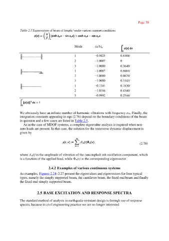
Table 2.5 Eigenvectors of beam of length / under various support conditions
Mode (a/b) n
1 −0.9825 0.8308/
2 −1.0007 0
3 −1.0000 0.3640/
1 −1.0007 0.8604/
2 −1.0000 0.0829/
3 −1.0000 0.3343/
1 −0.7341 0.7830/
2 −1.0184 0.4340/
3 −0.9992 0.2544/
We obviously have an infinite number of harmonic vibrations with frequency ω n. Finally, the
integration constants appearing in eqn (2.76) depend on the boundary conditions of the beam
in question and a few cases are listed in Table 2.5.
As in the case of MDOF systems, a complete eigenvalue analysis is required when non-
zero loads are present. In that case, the solution for the transverse dynamic displacement is
given by
(2.78)
where An(t) is the amplitude of vibration of the (uncoupled) nth oscillation component, which
is a function of the applied load, while Φ n(x) is the corresponding eigenvector.
2.4.2 Examples of various continuous systems
As examples, Figures 2.24–2.27 present the eigenvalues and eigenvectors for four typical
types, namely the simply supported beam, the cantilever beam, the fixed end beam and finally
the fixed end-simply supported beam.
2.5 BASE EXCITATION AND RESPONSE SPECTRA
The standard method of analysis in earthquake resistant design is through use of response
spectra, because in civil engineering practice we are no longer interested