
Page 84 - Dynamic Vision for Perception and Control of Motion
P. 84
3 Subjects and Subject Classes
68
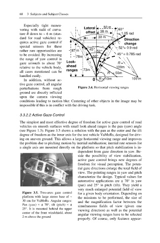
Especially tight maneu- 50 m
vering with radii of curva- Lateral 60°
offset ~ 38 m
ture R down to ~ 6 m (stan- = 1.05 rad
dard for road vehicles) re- ~ 30 m
Direction
quires active gaze control if change
special sensors for these ~ 52°= 0.9 rad
rather rare opportunities are ~ 87 m 45° ~ 52°
to be avoided. By increasing 45° = 0.785 rad
~ 78m 60°
the range of yaw control in
gaze azimuth to about 70° Look- R =
ahead
relative to the vehicle body, 100m
all cases mentioned can be ranges ~ 73m
R = 50m
handled easily.
In addition, without ac- 0 R = 10m 100 m
tive gaze control, all angular
perturbations from rough Figure 3.4. Horizontal viewing ranges
ground are directly inflicted
upon the camera viewing
conditions leading to motion blur. Centering of other objects in the image may be
impossible if this is in conflict with the driving task.
3.3.2.2 Active Gaze Control
The simplest and most effective degree of freedom for active gaze control of road
vehicles on smooth surfaces with small look-ahead ranges is the pan (yaw) angle
(see Figure 1.3). Figure 3.5 shows a solution with the pan as the outer and the tilt
degree of freedom as the inner axis for the test vehicle VaMoRs, designed for driv-
ing on uneven ground. This allows a large horizontal viewing range and improves
the problem due to pitching motion by inertial stabilization; inertial rate sensors for
a single axis are mounted directly on the platform so that pitch stabilization is in-
dependent from gaze direction in yaw. Be-
side the possibility of view stabilization,
active gaze control brings new degrees of
freedom for visual perception. The poten-
tial gaze directions enlarge the total field of
view. The pointing ranges in yaw and pitch
characterize the design. Typical values for
automotive applications are ± 70° in yaw
(pan) and 25° in pitch (tilt). They yield a
very much enlarged potential field of view
Figure 3.5. Two-axes gaze control for a given body orientation. Depending on
platform with large stereo base of ~ the missions to be performed, the size of
30 cm for VaMoRs. Angular ranges: and the magnification factor between the
Pan (yaw) § ± 70°, tilt (pitch) § ±
simultaneous fields of view (given one
25°. It is mounted behind the upper
viewing direction) as well as the potential
center of the front windshield, about angular viewing ranges have to be selected
2 m above the ground
properly. Of course, only features appear-