
Page 294 - Dynamics and Control of Nuclear Reactors
P. 294
296 APPENDIX E Frequency response analysis of linear systems
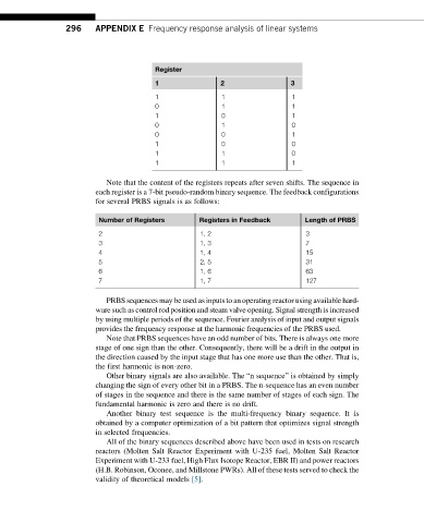
Register
1 2 3
1 1 1
0 1 1
1 0 1
0 1 0
0 0 1
1 0 0
1 1 0
1 1 1
Note that the content of the registers repeats after seven shifts. The sequence in
each register is a 7-bit pseudo-random binary sequence. The feedback configurations
for several PRBS signals is as follows:
Number of Registers Registers in Feedback Length of PRBS
2 1, 2 3
3 1, 3 7
4 1, 4 15
5 2, 5 31
6 1, 6 63
7 1, 7 127
PRBS sequences may be used as inputs to an operating reactor using available hard-
ware such as control rod position and steam valve opening. Signal strength is increased
by using multiple periods of the sequence. Fourier analysis of input and output signals
provides the frequency response at the harmonic frequencies of the PRBS used.
Note that PRBS sequences have an odd number of bits. There is always one more
stage of one sign than the other. Consequently, there will be a drift in the output in
the direction caused by the input stage that has one more use than the other. That is,
the first harmonic is non-zero.
Other binary signals are also available. The “n sequence” is obtained by simply
changing the sign of every other bit in a PRBS. The n-sequence has an even number
of stages in the sequence and there is the same number of stages of each sign. The
fundamental harmonic is zero and there is no drift.
Another binary test sequence is the multi-frequency binary sequence. It is
obtained by a computer optimization of a bit pattern that optimizes signal strength
in selected frequencies.
All of the binary sequences described above have been used in tests on research
reactors (Molten Salt Reactor Experiment with U-235 fuel, Molten Salt Reactor
Experiment with U-233 fuel, High Flux Isotope Reactor, EBR II) and power reactors
(H.B. Robinson, Oconee, and Millstone PWRs). All of these tests served to check the
validity of theoretical models [5].