
Page 112 - Dynamics of Mechanical Systems
P. 112
0593_C04*_fm Page 93 Monday, May 6, 2002 2:06 PM
Kinematics of a Rigid Body 93
i N N N N
Ri Si Yi Di
1
2
3
ψ φ θ
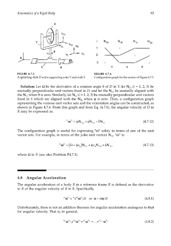
FIGURE 4.7.5 FIGURE 4.7.6
A spinning disk D and a supporting yoke Y and shaft S. Configuration graph for the system of Figure 4.7.5.
Solution: Let Ω be the derivative of a rotation angle θ of D in Y; let N (i = 1, 2, 3) be
Di
mutually perpendicular unit vectors fixed in D; and let the N be mutually aligned with
Di
the N when θ is zero. Similarly, let N (i = 1, 2, 3) be mutually perpendicular unit vectors
Yi
Si
fixed in S which are aligned with the N when ψ is zero. Then, a configuration graph
Ri
representing the various unit vector sets and the orientation angles can be constructed, as
shown in Figure 4.7.6. From this graph and from Eq. (4.7.6), the angular velocity of D in
R may be expressed as:
R D ˙ ˙
ωω= ˙ ψN + φN + θN (4.7.12)
R2 S3 Y1
R
D
The configuration graph is useful for expressing ω solely in terms of one of the unit
R
D
vector sets. For example, in terms of the yoke unit vectors N , ω is:
Yi
ωω= ( Ω + s ˙ ψ φ Y ) N 1 + c ˙ ψ N Y2 + φN Y3 (4.7.13)
R D ˙
φ
θ
˙
where Ω is (see also Problem P4.7.1).
4.8 Angular Acceleration
The angular acceleration of a body B in a reference frame R is defined as the derivative
in R of the angular velocity of B in R. Specifically,
αα = d ωω dt or = dωω dt (4.8.1)
αα
R B R R B
Unfortunately, there is not an addition theorem for angular acceleration analogous to that
for angular velocity. That is, in general,
R n
R 0 αα ≠ R 0 αα + R 1 αα +K + R n 1− αα R n (4.8.2)
R 2
R 1