
Page 129 - Dynamics of Mechanical Systems
P. 129
0593_C04*_fm Page 110 Monday, May 6, 2002 2:06 PM
110 Dynamics of Mechanical Systems
and
rψ
C
C
V = 0, a = ˙ 2 n (4.12.10)
3
Observe that even though the velocity of the contact point is zero, its acceleration is
not zero.
4.13 A Conical Thrust Bearing
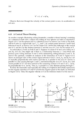
As another example illustrating rolling kinematics, consider a thrust bearing* consisting
of a cylindrical shaft with a conical end rolling on four spheres (or balls) as depicted in
Figure 4.13.1. Let the spheres roll in a cylindrical race R as shown. Let S refer to the shaft,
and let B refer to a typical ball. Let C , C , and C be contact points between S and B and
1 2 3
between B and R, as shown. Let G be the center of B. Let θ be the half-angle of the conical
end of S, and let a be the distance between G and the axis of S. Let r be the radius of B.
As noted above, B rolls on both R and S. Suppose we desire B to have pure rolling on S
(see Eq. (4.11.2)). One might ask if there is a relationship between a, r, and θ that will
produce pure rolling between B and S while maintaining rolling between B and R. To
answer this question, consider an analysis of the kinematics of B and S: Figure 4.13.2
shows an enlarged view of the contact region between B and S. Let n , n , and n be a set
1 2 3
of mutually perpendicular unit vectors such that n is parallel to the axis of S and n is
2 1
parallel to a line passing through G and C and intersecting the axis of S. Let n be a unit
3 ⊥
vector parallel to GC and thus normal to the contacting surfaces of B and S at C . Let n
1
be perpendicular to n and n . Thus, n is parallel to a cone element passing through C .
⊥
1
3
To study the kinematics and especially the rolling, it is helpful to first obtain expressions
for the angular velocities of S and B: Let Ω be the angular speed of the shaft S as indicated
in Figure 4.13.2. Then, the angular velocity of S in the reference frame R of the race is:
R S
ωω= Ωn (4.13.1)
2
S Ω S
n ⊥
n
n
2
B
b
θ B
C 1 θ C 1 n
1
G
r G C
C 2 n
2 3
R C 3
a C 3 a R
FIGURE 4.13.1 FIGURE 4.13.2
A conical thrust ball bearing. Ball and shaft geometry.
* This problem is discussed by Kane (4.1, 4.2) and Cabannes (4.5); see also Ramsey (4.6).