
Page 127 - Dynamics of Mechanical Systems
P. 127
0593_C04*_fm Page 108 Monday, May 6, 2002 2:06 PM
108 Dynamics of Mechanical Systems
ˆ
L n Z
D 3
n
3
θ N 3
L R
D n i S R 1 R D
ψ 2 2
N 1
1 G θ
φ
X r N 2 2 ψ
S 3
φ
ˆ
T n 1 n 2 Y N i n ˆ i n i d i
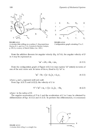
FIGURE 4.12.1 FIGURE 4.12.2
A circular disk rolling on a surface S. (Reprinted from Configuration graph orienting D in S.
Huston, R. L., and Liu, C. Q., Formulas for Dynamic Analysis,
p. 258, by courtesy of Marcel Dekker, Inc., 2001.)
From the addition theorem for angular velocity (Eq. (4.7.6)), the angular velocity of D
in S may be expressed as:
˙
˙
D
S ωω= φN 3 + ˆ 1 + ˙ ψn 2 (4.12.1)
θn
S
D
From the configuration graph of Figure 4.12.2 we may express ω entirely in terms of
one of the unit vector sets. In terms of the n (fixed in R ) ω is:
S
D
i
2
+
˙
S D ˙ ˙ ˙
ωω= θn +( ψ φ s ) n + c φ n (4.12.2)
1 θ 2 θ 3
where s and c represent sinθ and cosθ.
θ
θ
From Eqs. (4.11.5) and (4.12.2), the velocity of G is:
n )
V = ωω D × n r = r( ψφθ ˙ n (4.12.3)
−
˙
+
S
G
˙
s
r
3 θ 1 2
where r is the radius of D.
The angular acceleration of D in S and the acceleration of G in S may be obtained by
differentiation of Eqs. (4.12.2) and (4.12.3). To perform this differentiation, it is necessary
Z
n
3
D
G
P
ψ r
X
FIGURE 4.12.3
A circular disk rolling in a straight line. n 1