
Page 135 - Dynamics of Mechanical Systems
P. 135
0593_C04*_fm Page 116 Monday, May 6, 2002 2:06 PM
116 Dynamics of Mechanical Systems
Section 4.6 Differentiation in Different Reference Frames
P4.6.1: Refer again to Problem P4.5.1. Let the origin O of the reference frame fixed in body
B have a velocity in reference frame R given by:
R O
V = 8 n − 6 n + 5 n m s
x y z
ˆ
ˆ
P
P
Next, let be a point that moves relative to B such that the location of relative to O is
ˆ
given by the vector OP as:
ˆ
OP = 4t n − 3t 2 n + 9t 3 n m
x y z
ˆ
P
Find the velocity of in R at times t = 0, 1, and 2 sec.
P4.6.2: See Example 4.6.1. Suppose the rocket is launched from the Earth at a latitude of
40° North. Find the velocity of R in the astronomical frame A.
Section 4.7 Addition Theorem for Angular Velocity
P4.7.1: See Example 4.7.1. Using the configuration graph of Figure 4.7.6, express ωω ωω of
R
D
Eq. (4.7.12) in terms of (a) N , (b) N , and (c) N .
Ri
Di
Si
P4.7.2: Using Eq. (4.7.6), show that:
ωω =− ωω
R B B R
for a body B moving in a reference frame R.
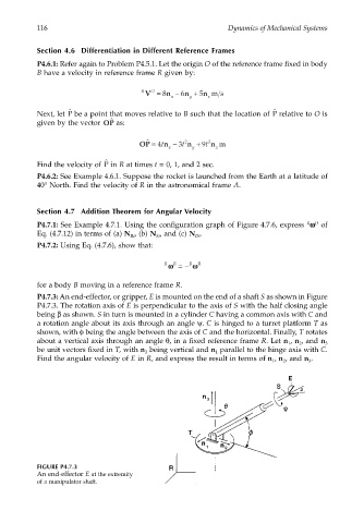
P4.7.3: An end-effector, or gripper, E is mounted on the end of a shaft S as shown in Figure
P4.7.3. The rotation axis of E is perpendicular to the axis of S with the half closing angle
being β as shown. S in turn is mounted in a cylinder C having a common axis with C and
a rotation angle about its axis through an angle ψ. C is hinged to a turret platform T as
shown, with φ being the angle between the axis of C and the horizontal. Finally, T rotates
about a vertical axis through an angle θ, in a fixed reference frame R. Let n , n , and n 3
2
1
be unit vectors fixed in T, with n being vertical and n parallel to the hinge axis with C.
3
1
Find the angular velocity of E in R, and express the result in terms of n , n , and n .
3
1
2
FIGURE P4.7.3
An end-effector E at the extremity
of a manipulator shaft.