
Page 178 - Dynamics of Mechanical Systems
P. 178
0593_C05_fm Page 159 Monday, May 6, 2002 2:15 PM
Planar Motion of Rigid Bodies — Methods of Analysis 159
Section 5.4 Instant Center, Points of Zero Velocity
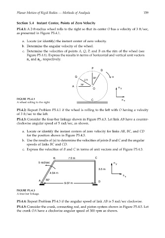
P5.4.1: A 2-ft-radius wheel rolls to the right so that its center O has a velocity of 3 ft/sec,
as presented in Figure P5.4.1.
a. Locate (or identify) the instant center of zero velocity.
b. Determine the angular velocity of the wheel.
c. Determine the velocities of points A, Q, P, and B on the rim of the wheel (see
Figure P5.4.1). Express the results in terms of horizontal and vertical unit vectors
n and n , respectively.
x
y
P
B
Q ω
30°
2 ft
30°
A
O n y
FIGURE P5.4.1 C n x
A wheel rolling to the right.
P5.4.2: Repeat Problem P5.4.1 if the wheel is rolling to the left with O having a velocity
of 3 ft/sec to the left.
P5.4.3: Consider the four-bar linkage shown in Figure P5.4.3. Let link AB have a counter-
clockwise angular speed of 5 rad/sec, as shown.
a. Locate or identify the instant centers of zero velocity for links AB, BC, and CD
for the position shown in Figure P5.4.3.
b. Use the results of (a) to determine the velocities of joints B and C and the angular
speeds of links BC and CD.
c. Express the velocities of B and C in terms of unit vectors and of Figure P5.4.3.
B 7.0 m C
5 rad/sec n
y
3.5 m
4.04 m
n
x
A 60° D
9.02 m
FIGURE P5.4.3
A four-bar linkage.
P5.4.4: Repeat Problem P5.4.3 if the angular speed of link AB is 5 rad/sec clockwise.
P5.4.5: Consider the crank, connecting rod, and piston system shown in Figure P5.4.5. Let
the crank OA have a clockwise angular speed of 300 rpm as shown.