
Page 373 - Dynamics of Mechanical Systems
P. 373
0593_C11_fm Page 354 Monday, May 6, 2002 2:59 PM
354 Dynamics of Mechanical Systems
θ
L
O
x P P(m)
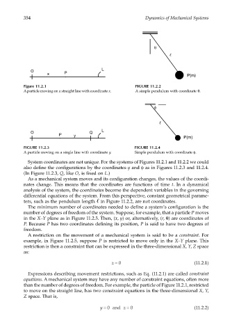
Figure 11.2.1 FIGURE 11.2.2
A particle moving on a straight line with coordinate x. A simple pendulum with coordinate θ.
φ
O Q L
P y
P(m)
FIGURE 11.2.3 FIGURE 11.2.4
A particle moving on a single line with coordinate y. Simple pendulum with coordinate φ.
System coordinates are not unique. For the systems of Figures 11.2.1 and 11.2.2 we could
also define the configurations by the coordinates y and φ as in Figures 11.2.3 and 11.2.4.
(In Figure 11.2.3, Q, like O, is fixed on L.)
As a mechanical system moves and its configuration changes, the values of the coordi-
nates change. This means that the coordinates are functions of time t. In a dynamical
analysis of the system, the coordinates become the dependent variables in the governing
differential equations of the system. From this perspective, constant geometrical parame-
ters, such as the pendulum length in Figure 11.2.2, are not coordinates.
The minimum number of coordinates needed to define a system’s configuration is the
number of degrees of freedom of the system. Suppose, for example, that a particle P moves
in the X–Y plane as in Figure 11.2.5. Then, (x, y) or, alternatively, (r, θ) are coordinates of
P. Because P has two coordinates defining its position, P is said to have two degrees of
freedom.
A restriction on the movement of a mechanical system is said to be a constraint. For
example, in Figure 11.2.5, suppose P is restricted to move only in the X–Y plane. This
restriction is then a constraint that can be expressed in the three-dimensional X, Y, Z space
as:
z = 0 (11.2.1)
Expressions describing movement restrictions, such as Eq. (11.2.1) are called constraint
equations. A mechanical system may have any number of constraint equations, often more
than the number of degrees of freedom. For example, the particle of Figure 11.2.1, restricted
to move on the straight line, has two constraint equations in the three-dimensional X, Y,
Z space. That is,
y = 0 and z = 0 (11.2.2)