
Page 394 - Dynamics of Mechanical Systems
P. 394
0593_C11_fm Page 375 Monday, May 6, 2002 2:59 PM
Generalized Dynamics: Kinematics and Kinetics 375
Comparing Eq. (11.7.24) with Eqs. (11.7.14) to (11.7.17), we see that the results are
consistent.
11.8 Forces That Do Not Contribute to the Generalized Forces
In the example of the foregoing section we observed that some of the forces exerted on
the system did not contribute to the generalized forces. These noncontributing forces were
exerted at the pin and across the smooth surface in the interior of the tube T. If it had
been known in advance that these forces would not contribute to the generalized forces,
then we could have saved the computation labor of evaluating their contribution — only
to find it to be zero. That is, if we could identify noncontributing forces at the onset of
the analysis, we could ignore those forces in the remainder of the analysis.
It happens that it is possible to identify classes of forces that will not contribute to the
generalized forces. These are forces exerted at fixed pins, forces exerted at points of zero
velocity, forces exerted across smooth surfaces interior to a mechanical system, and forces
exerted across smooth surfaces whose motion is prescribed.
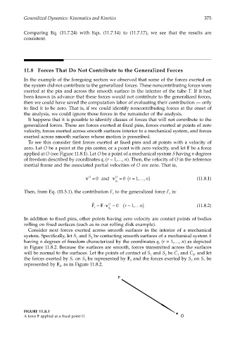
To see this consider first forces exerted at fixed pins and at points with a velocity of
zero. Let O be a point at the pin center, or a point with zero velocity, and let F be a force
applied at O (see Figure 11.8.1). Let O be a point of a mechanical system S having n degrees
of freedom described by coordinates q (r = 1,…, n). Then, the velocity of O in the reference
r
inertial frame and the associated partial velocities of O are zero. That is,
O
O
1
0
v = 0 and v = ( r = …, n) (11.8.1)
,
q r ˙
Then, from Eq. (11.5.1), the contribution F to the generalized force F is:
r r
ˆ
F =⋅ O ( r = 1 ,… n) (11.8.2)
F v = 0
r ˙ q r
In addition to fixed pins, other points having zero velocity are contact points of bodies
rolling on fixed surfaces (such as in our rolling disk example).
Consider next forces exerted across smooth surfaces in the interior of a mechanical
system. Specifically, let S and S be contacting smooth surfaces of a mechanical system S
1 2
having n degrees of freedom characterized by the coordinates q (r = 1,…, n) as depicted
r
in Figure 11.8.2. Because the surfaces are smooth, forces transmitted across the surfaces
will be normal to the surfaces. Let the points of contact of S and S be C and C , and let
1 2 1 2
the forces exerted by S on S be represented by F and the forces exerted by S on S be
1 2 2 2 1
represented by F , as in Figure 11.8.2.
1
F
FIGURE 11.8.1
A force F applied at a fixed point O. O