Page 555 - Dynamics of Mechanical Systems
P. 555

0593_C15_fm  Page 536  Tuesday, May 7, 2002  7:05 AM


                       536                                                 Dynamics of Mechanical Systems


                       Section 15.4 Dynamic Balancing: Arbitrarily Shaped Rotating Bodies
                       P15.4.1: Suppose n , n , and n  are mutually perpendicular unit vectors fixed in a body B,
                                       1
                                          2
                                                 3
                       and suppose that B is intended to be rotated with a constant speed Ω about an axis X
                       which passes through the mass center G of B and which is parallel to n . Let n , n , and
                                                                                       1
                                                                                              1
                                                                                                 2
                       n  be nearly parallel to principal inertia directions of B for G so that the components I  of
                                                                                                   ij
                        3
                       the inertia dyadic of B for G relative to n , n , and n  are:
                                                                     3
                                                              2
                                                           1
                                                                   .
                                                   18    −01.    025 
                                                                           2
                                               I = −01.    12    −015.   slug ft
                                               ij                    
                                                   0 25.  −0 15.  6   
                       Show that with this configuration and inertia dyadic that B is dynamically out of balance.
                       Next, suppose we intend to balance B by the addition of two 12-oz. weights P and  P ˆ
                       placed opposite one another about the mass center G. Determine the coordinates of P
                           ˆ
                           P
                       and   relative to the X-, Y-, and Z-axes with origin at G and parallel to n , n , and n .
                                                                                                    3
                                                                                             2
                                                                                          1
                       P15.4.2: Repeat Problem P15.4.1 if the inertia dyadic components are:
                                                     30   −02.   −03.  
                                                                          2
                                                I = −02.    20    025  kg m
                                                                   .
                                                 ij                 
                                                            .
                                                     −  03.  025  10   
                                                ˆ
                       and if the masses of P and   are each 0.5 kg.
                                               P
                       P15.4.3: Repeat Problems P15.4.1 and P15.4.2 if B is rotating about the Z-axis instead of
                       the X-axis.
                       Section 15.5 Balancing Reciprocating Machines
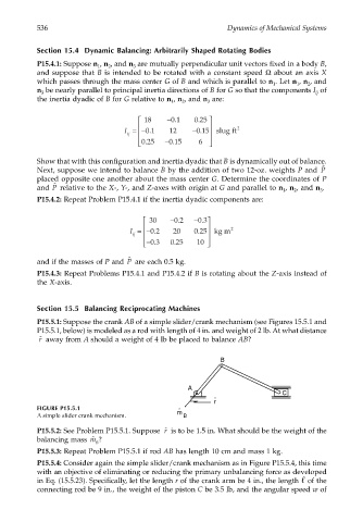
                       P15.5.1: Suppose the crank AB of a simple slider/crank mechanism (see Figures 15.5.1 and
                       P15.5.1, below) is modeled as a rod with length of 4 in. and weight of 2 lb. At what distance
                       ˆ r   away from A should a weight of 4 lb be placed to balance AB?


                                                                         B


                                                                A
                                                                                          C
                                                                       ˆ
                                                                       r
                       FIGURE P15.5.1                        ˆ
                       A simple slider crank mechanism.      m  B
                       P15.5.2: See Problem P15.5.1. Suppose   is to be 1.5 in. What should be the weight of the
                                                          ˆ r
                       balancing mass  ˆ m  ?
                                       B
                       P15.5.3: Repeat Problem P15.5.1 if rod AB has length 10 cm and mass 1 kg.
                       P15.5.4: Consider again the simple slider/crank mechanism as in Figure P15.5.4, this time
                       with an objective of eliminating or reducing the primary unbalancing force as developed
                       in Eq. (15.5.23). Specifically, let the length r of the crank arm be 4 in., the length   of the
                       connecting rod be 9 in., the weight of the piston C be 3.5 lb, and the angular speed w of
   550   551   552   553   554   555   556   557   558   559   560