
Page 550 - Dynamics of Mechanical Systems
P. 550
0593_C15_fm Page 531 Tuesday, May 7, 2002 7:05 AM
Balancing 531
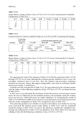
TABLE 15.9.4
Engine Balance: Listing of Terms of Eqs. (15.7.8) to (15.7.11) for the Connecting Rod/Crankshaft
Configuration of Table 15.9.2
i φφ φ φ (°) cosφφ φφ i sinφφ φφ i cos2φφ φφ i sin2φφ φφ i (i – 1)cosφφ φφ i (i – 1)sinφφ φφ i (i – 1)cos2φφ φφ i (i – 1)sin2φφ φφ i
i
1 0 1 0 1 0 0 0 0 0
2 90 0 1 –1 0 0 1 –1 0
3 180 –1 0 1 0 –2 0 2 0
4 270 0 –1 –1 0 0 –3 –3 0
Totals 0 0 0 0 –2 –2 –2 0
TABLE 15.9.5
Cylinder Strokes for Various Crankshaft Angles for 0, 90, 270, and 180° Connecting Rod Spacing
Connecting
Rod Crank Crankshaft Rotation/Stroke Type
Cylinder Angle (°) 0 to 180° 180 to 360° 360 to 540° 540 to 720°
1 0 Power Exhaust Intake Compression
2 90 Intake Compression Power Exhaust Intake
3 270 Exhaust Intake Compression Power Exhaust
4 180 Compression Power Exhaust Intake
TABLE 15.9.6
Engine Balance: Listing of Terms of Eqs. (15.7.8) to (15.7.11) for the Connecting Rod/Crankshaft
Configuration of Table 15.9.5
i φφ φ φ (°) cosφφ φφ i sinφφ φφ i cos2φφ φφ i sin2φφ φφ i (i – 1)cosφφ φφ (i – 1)sinφφ φφ i (i – 1)cos2φφ φφ i (i – 1)sin2φφ φφ i
i
i
1 0 1 0 1 0 0 0 0 0
2 90 0 1 –1 0 0 1 –1 0
3 270 0 –1 –1 0 0 –2 –2 0
4 180 –1 0 1 0 –3 0 3 0
Totals 0 0 0 0 –3 –1 0 0
By comparing the totals of the columns of Table 15.9.3 with the expressions of Eq. (15.7.8)
through (15.7.11) we see that, although the resultant primary unbalance force is zero, the
secondary unbalance force is not zero. Also, the primary and secondary unbalance
moments are nonzero. Hence, this engine configuration, even with its uniformly distrib-
uted power strokes, is unbalanced.
Consider next the arrangement of Table 15.9.2. By again identifying the cylinder number
with the index i of the balancing conditions of Eqs. (15.7.8) to (15.7.11), we obtain the data
of Table 15.9.4.
In this case, we see that both the resultants of both the primary and secondary inertia
forces are zero (or balanced), but the resultant primary and secondary moments of these
forces are not zero, which still leaves an engine unbalance. In comparing the results of
Table 15.9.4 with those of Table 15.9.3, however, we see that there is a marked improvement
with the stroke arrangement of Table 15.9.2 compared to that of Table 15.9.1
This raises the question as to whether we improve the balance even further by moving
away from both the uniform power stroke design of Table 15.9.1 and the crankshaft
symmetry design of Table 15.9.2. To answer this question, consider the crankshaft/con-
necting rod configuration of Table 15.9.5 (see Reference 15.8). Then, Table 15.9.6 provides
a listing of data for the balancing conditions of Eqs. (15.7.8) to (15.7.11).