
Page 549 - Dynamics of Mechanical Systems
P. 549
0593_C15_fm Page 530 Tuesday, May 7, 2002 7:05 AM
530 Dynamics of Mechanical Systems
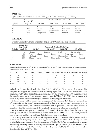
TABLE 5.9.1
Cylinder Strokes for Various Crankshaft Angles for 180° Connecting Rod Spacing
Connecting Crankshaft Rotation/Stroke Type
Rod Crank
Cylinder Angle (°) 0 to 180° 180 to 360° 360 to 540° 540 to 720°
1 0 Power Exhaust Intake Compression
2 180 Exhaust Intake Compression Power
3 360 Intake Compression Power Exhaust
4 540 Compression Power Exhaust Intake
TABLE 15.9.2
Cylinder Strokes for Various Crankshaft Angles for 90° Connecting Rod Spacing
Connecting
Rod Crank Crankshaft Rotation/Stroke Type
Cylinder Angle (°) 0 to 180° 180 to 360° 360 to 540° 540 to 720°
1 0 Power Exhaust Intake Compression
2 90 Power Exhaust Intake Compression Power
3 180 Exhaust Intake Compression Power
4 270 Exhaust Intake Compression Power Exhaust
TABLE 15.9.3
Engine Balance: Listing of Terms of Eqs. (15.7.8) to (15.7.11) for the Connecting Rod/Crankshaft
Configuration of Table 15.9.1
i φφ φ φ (°) cosφφ φφ i sinφφ φφ i cos2φφ φφ i sin2φφ φφ i (i – 1)cosφφ φφ (i – 1)sinφφ φφ (i – 1)cos2φφ φφ i (i – 1)sin2φφ φφ i
i
i
i
1 0 1 0 1 0 0 0 0 0
2 180 –1 0 1 0 –1 0 1 0
3 360 1 0 1 0 2 0 2 0
4 540 –1 0 1 0 –3 0 3 0
Totals 0 0 4 0 –2 0 6 0
rods along the crankshaft will directly affect the stability of the engine. To explore this,
suppose we stagger the power strokes uniformly. Specifically, because a four-stroke cycle
consumes 720°, let us space the connecting rods on the crankshaft at 180° intervals. Then,
the angular position and strokes are those as listed in Table 15.9.1. With this arrangement,
there is a power stroke occurring at all times during engine operation.
A disadvantage of this crankshaft arrangement, however, is that there are orientations
of the crankshaft for which the pistons are all either in an uppermost, or top-dead-center
(TDC), or lowermost, or bottom-dead-center (BDC), position. These orientations could
interfere with the functioning of the engine by producing a locked crankshaft.
An alternative arrangement, avoiding crankshaft lock, would be to have the connecting
rods spaced at 90° intervals along the crankshaft as in Table 15.9.2. This configuration,
however, does not have a uniform distribution of power strokes.
The arrangement of the strokes and, in particular, the occurrence of the power strokes,
is often called the firing order of the engine. To explore the effect of the firing order on
engine balancing, consider first the sequence of Table 15.9.1. We can evaluate the engine
balance by referring to the balancing conditions of Eqs. (15.7.8) to (15.7.11). That is, if we
identify the index i with the cylinder number, then from Table 15.9.1 we can immediately
develop the data of Table 15.9.3.